Variable engine valve control system

a valve control system and variable technology, applied in the direction of valve arrangements, machines/engines, non-mechanical valves, etc., can solve the problems of variable lift, inability to provide variable lift, and general complexity of typical electrohydraulic valve control systems, so as to reduce the complexity and cost of the system, the effect of less expensiv

Inactive Publication Date: 2003-01-14
VISTEON GLOBAL TECH INC
View PDF21 Cites 32 Cited by
  • Summary
  • Abstract
  • Description
  • Claims
  • Application Information

AI Technical Summary

Benefits of technology

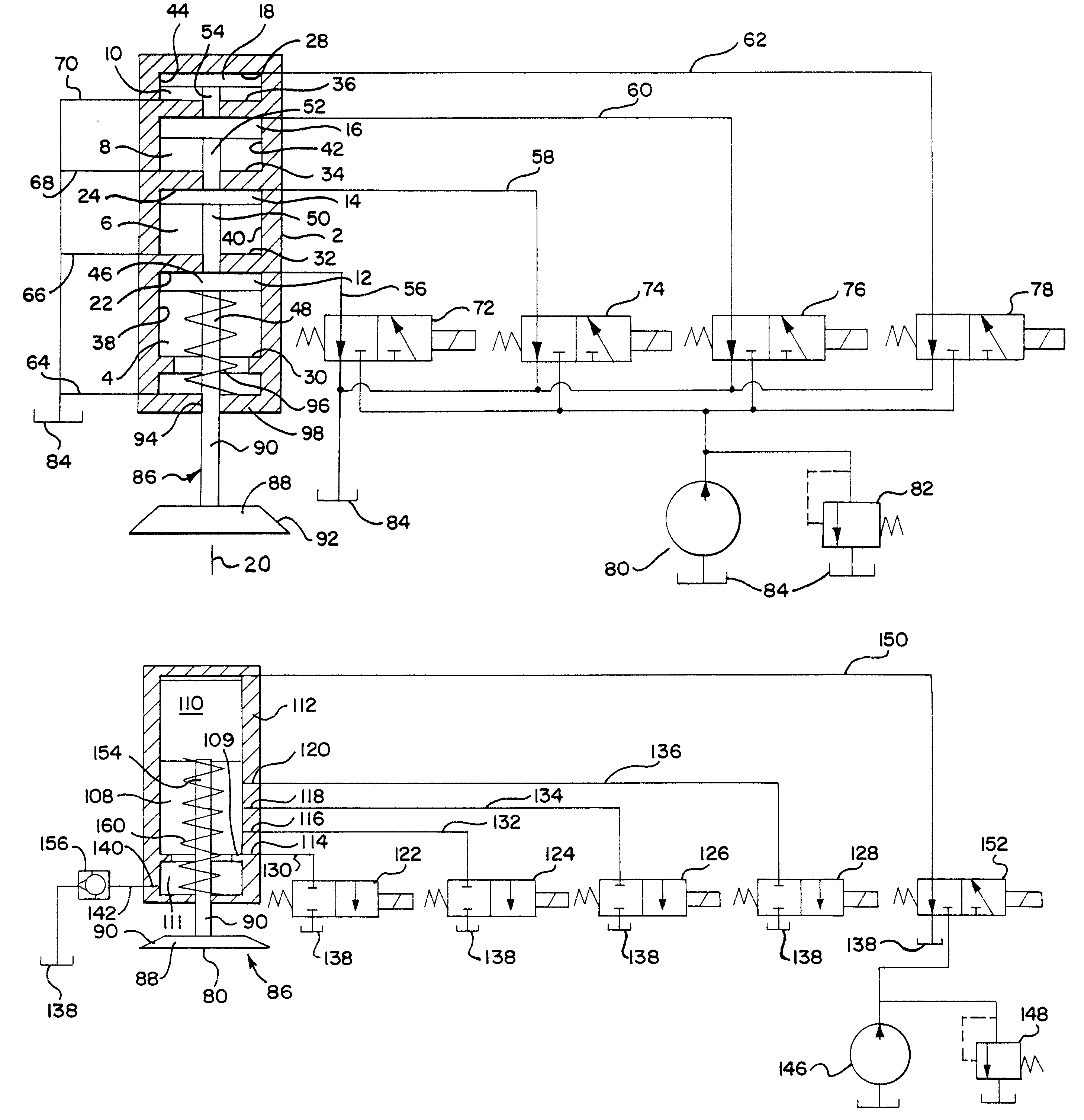
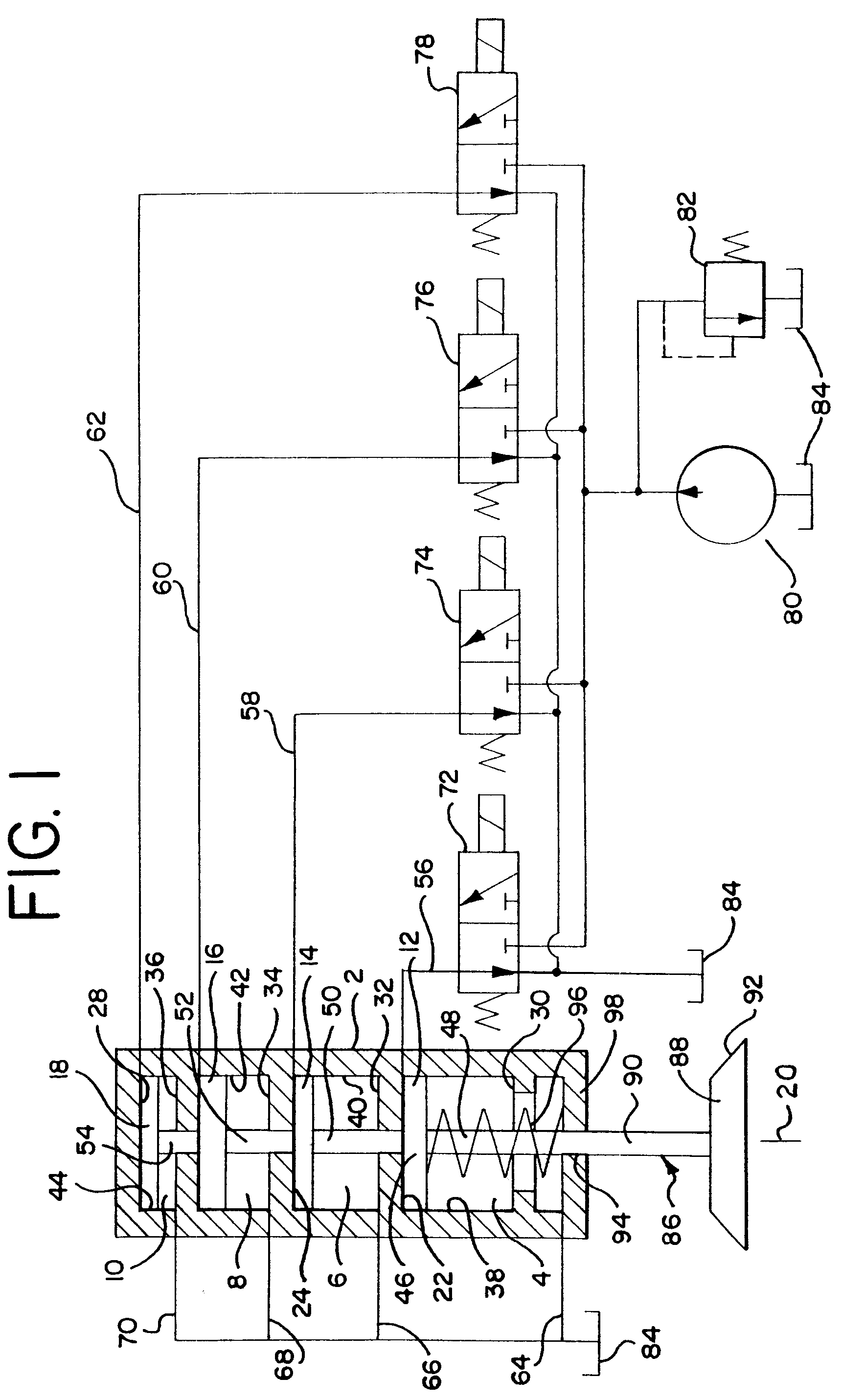
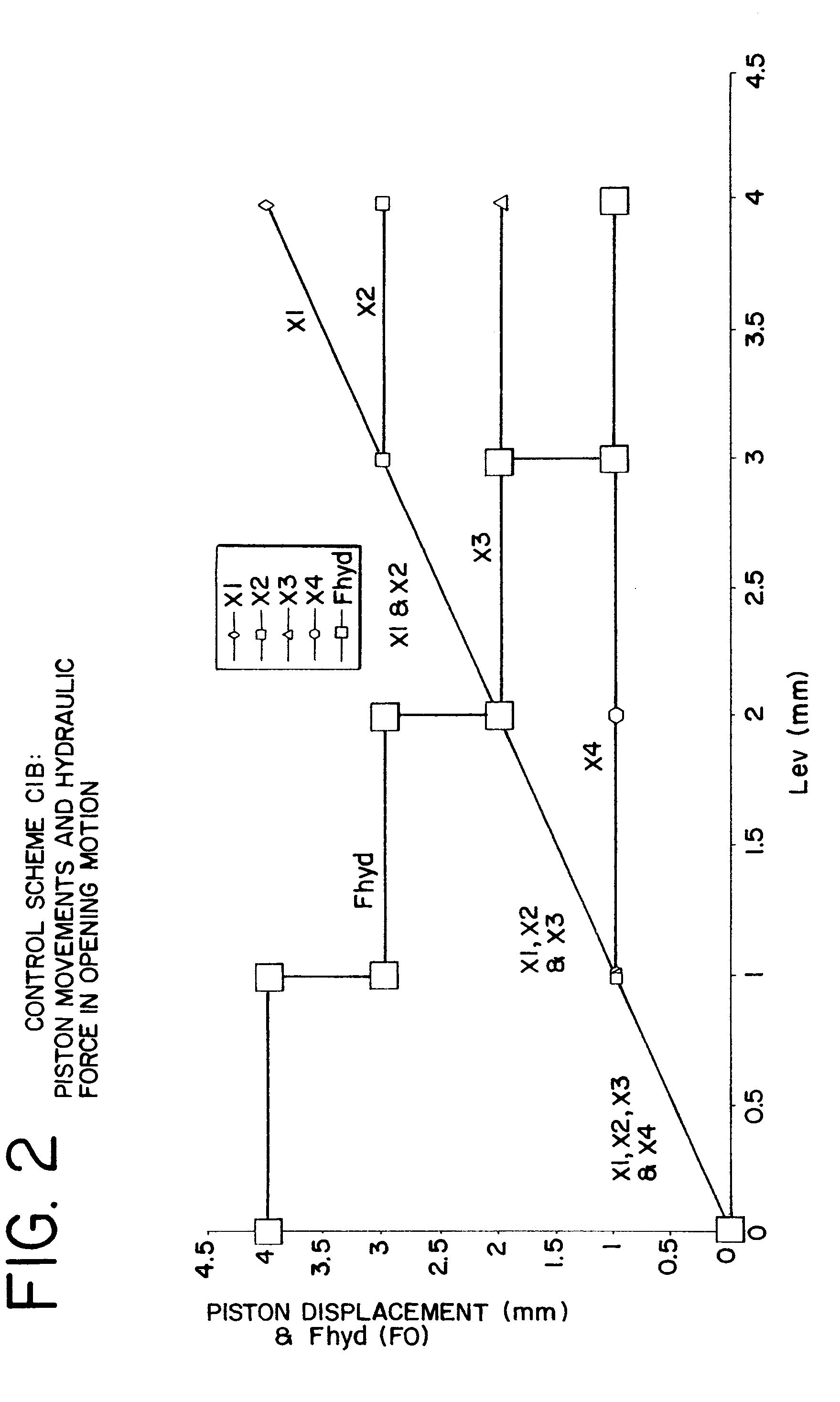
The present inventions provide significant advantages over other valve control systems, and methods for controlling valve engines. For example, each of the present embodiments of the valve control system is configured as an electrohydraulic DLVT (discrete lift, variable timing) system, which achieves discrete lift and variable timing for engine valves. By employing a discrete lift control, relatively simple hydraulic valves can be used, which eliminates the need for position sensing and feedback controls in the system and thereby substantially reduces the complexity and cost of the system. In this way, a system employing discrete lift control is simpler, less expensive and more robust than an electrohydraulic VVLT system, when used in most applications. In addition, by providing a plurality of discrete lifts, the system can closely match the performance of the VVLT system under most operating conditions.

Problems solved by technology

One important limitation of such mechanical VVLT systems is that the timing and lift variations are not independent.
However, such systems do not provide for variable lift.
However, typical electrohydraulic VVLT systems are generally rather complex, can be expensive to manufacture, and typically are not as reliable or robust as mechanical systems due to their relative complexity.

Method used


Image

  • Variable engine valve control system
  • Variable engine valve control system
  • Variable engine valve control system

Examples


Embodiment Construction

As used herein, the term "discrete" means "controlled in steps," i.e., not infinitely variable. The term "variable" as used herein means "infinitely" variable or adjustable. The term "longitudinal" as used herein means of or relating to length or the lengthwise dimension. The term "plurality" as used herein means two or more.

The terms "top," "bottom," "upper," "lower," "lowermost," and "uppermost" as used herein are intended to indicate the various directions or positions of, or various components within, the housing and cylinders relative to the position of the engine valve, regardless of the orientation of the housing and cylinders, and are not to be interpreted as requiring any component to have a specific orientation along a vertical axis. Rather, one of skill in the art should understand that the housing, cylinders and pistons can be oriented in any direction, including a horizontal and vertical orientation, with the engine valve located at a top, bottom, or opposite side there...


PUM


Abstract

A discrete lift, variable timing (DLVT) engine valve control system for an internal combustion engine includes a plurality of electrohydraulic valves. The plurality of electrohydraulic valves are operable between at least an open and closed position. Each of the plurality of electrohydraulic valves is operable independently of the other of the plurality of electrohydraulic valves. In one preferred embodiment, a selected combination of the plurality of electrohydraulic valves are selectively operated between at least the open and closed positions to move a selected combination of a plurality of pistons disposed in a selected combination of a plurality of axially spaced cylinders positioned serially one on top of the other. In an alternative preferred embodiment, a selected combination of the plurality of electrohydraulic valves are selectively operated between at least the open and closed positions to open a selected combination of longitudinally spaced exhaust ports communicating with a cylinder. Methods for controlling an engine valve in an internal combustion engine also are provided.

Description

The present invention relates generally to a variable engine valve control system, and in particular, to a discrete lift, variable timing engine valve control system.In general, various throttle-less systems can be used to actively control engine valves through the use of variable lift and / or variable timing so as to achieve various improvements in engine performance, fuel economy, reduced emissions, and other like aspects. Typically, such systems are mechanical VVLT (variable valve-lift and timing), electrohydraulic VVLT, or electro / mechanical VVT (variable valve-timing). In general, mechanical VVLT systems are cam-based systems, which may have additional phasers, cams and linkage. One important limitation of such mechanical VVLT systems is that the timing and lift variations are not independent. Electro / mechanical VVT systems generally replace the cam in the mechanical VVLT system with an electro-mechanical actuator. However, such systems do not provide for variable lift.In contra...

Claims


Application Information

Patent Timeline
Patent Type & Authority Patents(United States)
IPC IPC(8): F01L9/00F01L9/02F01L9/10
CPCF01L9/02F01L9/10
Inventor LOU, ZHENG
Owner VISTEON GLOBAL TECH INC
Why Eureka
Try Eureka