
Transmitter with a sliding compression point

a compression point and transmitter technology, applied in the direction of amplifier modification, gain control, amplifier modification to reduce noise influence, etc., can solve the problem of unsatisfactory amounts of energy present, and achieve the effect of power saving, maximum power saving, and reducing peak-to-averag

Inactive Publication Date: 2003-01-14
NXP BV
View PDF2 Cites 3 Cited by
  • Summary
  • Abstract
  • Description
  • Claims
  • Application Information

AI Technical Summary

Problems solved by technology

Non-linear operation, in addition to distortion and loss of information, causes an increase in intermodulation products that cause undesirable amounts of energy to be present in frequency bands other than the one intended for use.
Driving the power amplifier into saturation increases efficiency of the power amplifier but also causes intermodulation products to rise, so a tradeoff is needed between high efficiency and low intermodulation products.

Method used


Image

  • Transmitter with a sliding compression point
  • Transmitter with a sliding compression point

Examples


Embodiment Construction

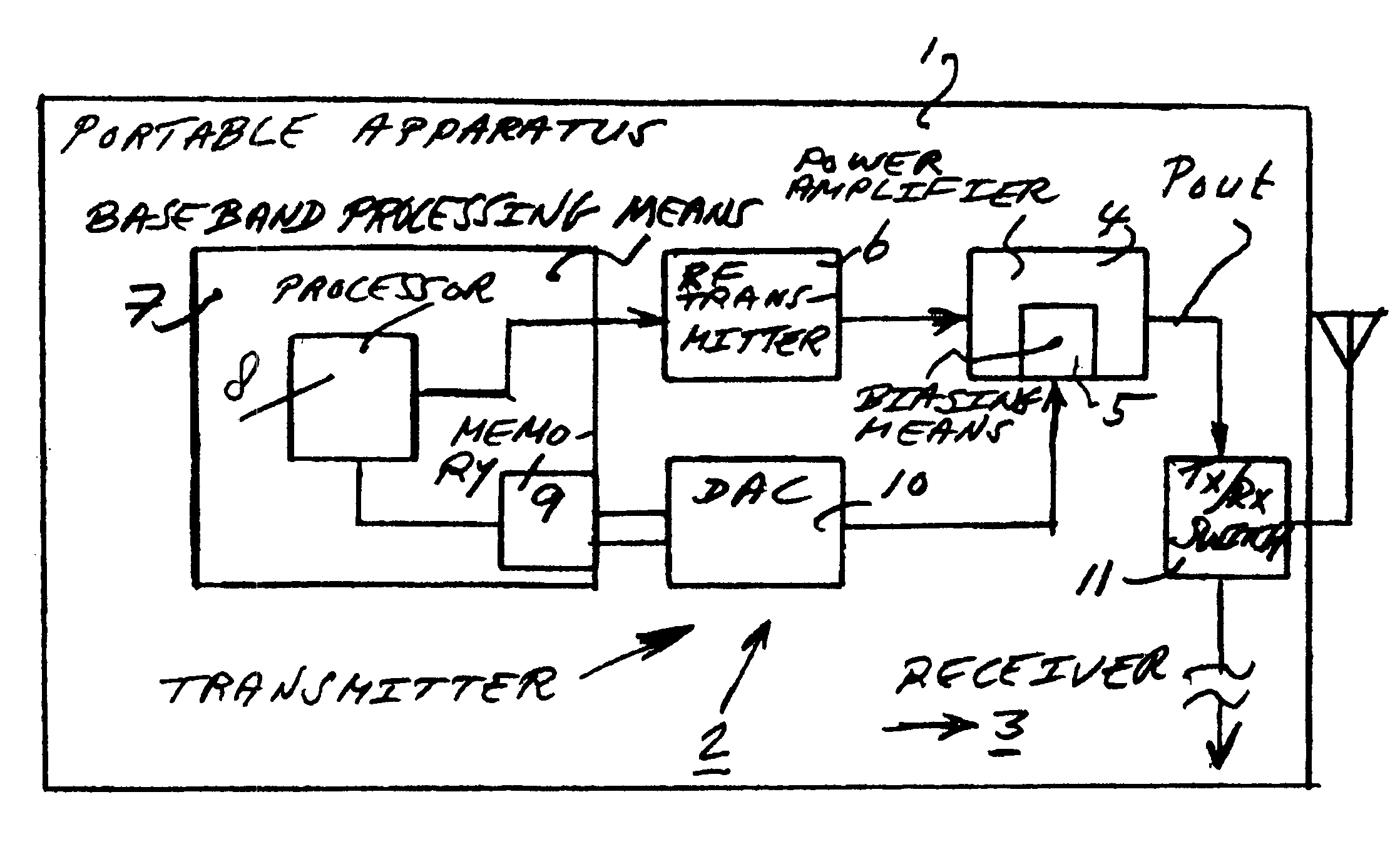
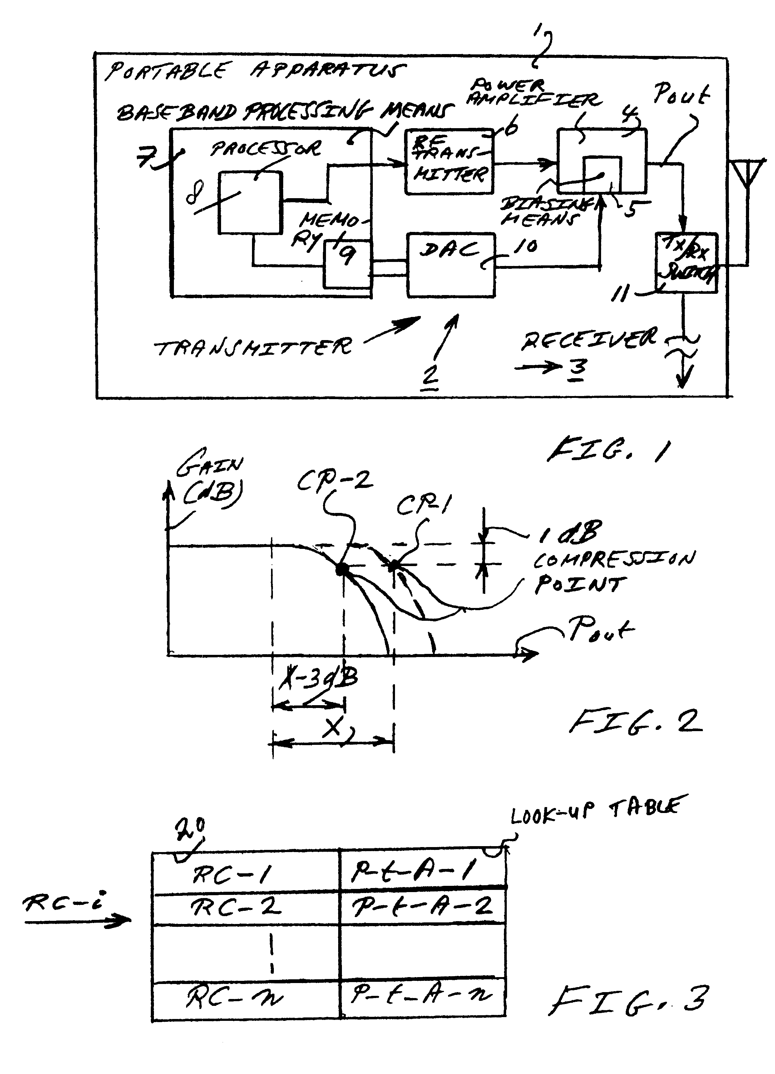
FIG. 1 is a block diagram of a portable apparatus 1 according to the invention. The portable apparatus 1 can be a mobile phone, a PDA with a wireless extension, a PC with a wireless extension, or a combination of any other radio frequency device with other devices. The portable apparatus 1 comprises a transmitter 2, and, optionally, a receiver 3 (not shown in detail here). Transmitter 2, and, optionally receiver 3, may be included in a module for such a portable apparatus 1 that may be sold separately by a module manufacturer to an apparatus manufacturer. Transmitter 2 comprises a power amplifier 4 with biasing means 5 to set and / or adjust a biasing current of power amplifier 4, more particularly a compression point of power amplifier 4. Transmitter 2 further comprises a radio frequency transmitter 6 and a base band processing means 7. Base band processing means 7 comprises a processor with memory 9 that comprises a look-up table according to the invention. Transmitter 2 further com...


PUM


Abstract

A transmitter has a power amplifier amplifying a radio frequency transmit signal. The radio frequency transmit signal is a non-constant envelope modulated signal. The power amplifier has a first compression point. In a method for sliding a compression point in the transmitter, the power amplifier is operated at a first backoff from the first compression point such that a given adjacent channel power ratio requirement is met for a first peak-to-average ratio of the radio frequency transmit signal. The first compression point is slide to a second compression point for a second peak-to-average ratio of the radio frequency transmit signal, the second compression point being lower than the first compression point. The first and second peak-to-average ratios are dependent on information content of the non-constant envelope modulated signal.

Description

1. Field of the InventionThe invention relates to a transmitter with a power amplifier that amplifies a radio frequency transmit signal that is a non-constant envelope modulated signal.The invention further relates to a portable apparatus including such a transmitter, to a module including such a transmitter, and to a method for sliding a compression point in such a transmitter. Such transmitters may be used in CDMA systems referred to as linear modulation systems, or any other suitable device or system with non-constant envelope modulated signals requiring linear modulation, in which information is carried as phase and amplitude modulated information.2. Description of the Related ArtIn U.S. Pat. No. 5,936,464 a method for reducing distortion in a high efficiency power amplifier is disclosed. The power amplifier is included in a communication device that transmits signals having information in both amplitude and phase. Such transmission requires low distortion to be achieved by so-c...

Claims


Application Information

Patent Timeline
Patent Type & Authority Patents(United States)
IPC IPC(8): H03F1/02H04B1/04H03F3/24
CPCH03F1/0261H04B1/04
Inventor DUPERRAY, DAVID
Owner NXP BV
Learn More