Ultrasonic flowmeter and ultrasonic generator/detector

a flowmeter and ultrasonic technology, applied in the direction of generator/motor, liquid/fluent solid measurement, instruments, etc., can solve the problems of shortening the measurement time of flow rate, difficult to estimate the flow velocity distribution at high precision, and increasing the cost of the ultrasonic circuit, etc., to achieve excellent high speed response and precision, and high sensitivity

Inactive Publication Date: 2003-01-21
PANASONIC CORP
View PDF20 Cites 42 Cited by
  • Summary
  • Abstract
  • Description
  • Claims
  • Application Information

AI Technical Summary

Benefits of technology

The invention is to solve the problems of the prior art, and it is an object thereof to present a compact ultrasonic flowmeter and ultrasonic transducer, advanced in degrees of freedom of selection of dimensions and frequency of ultrasonic transducer, high in sensitivity, and excellent in high speed response and precision.

Problems solved by technology

(1) In a first problem, since the piezoelectric plate used in the ultrasonic transducer is cylindrical, when the thickness vibration or radial vibration of a disk is utilized, if a low frequency is selected, the diameter becomes large, and the ultrasonic transducer is large in size, so that the ultrasonic flowmeter cannot be reduced in size. When using the ultrasonic transducer of small size, the frequency must be high, and effects of attenuation due to propagation of ultrasonic wave are significant, which causes to increase the cost of circuit of the ultrasonic flowmeter. Accordingly, when an ultrasonic transducer of a proper size suited to the ultrasonic flowmeter is selected, the selection of the frequency is limited. Moreover, the electromechanical coupling coefficient of thickness vibration of disk is Kt, and the electromechanical coupling coefficient of radial vibration is Kp, which were smaller than the electromechanical coupling coefficient of longitudinal vibration of K33, and hence the sensitivity was low. Yet, since the cylindrical piezoelectric plate 57 was not provided with constituent material such as backing layer for lowering the mechanical Q, only ultrasonic pulses of long ringing could be transmitted, and it was hard to shorten the flow rate measuring time.
(2) In a second problem, since the section of the cylindrical tube 51 is circular, in spite of the two-dimensional flow velocity distribution in which the flow velocity V near the center is fast and the flow velocity V of the outer side is slow, at the flow velocity V obtained by two confronting sets of ultrasonic transducer, it is hard to reflect the flow velocity distribution of the entire section of the cylindrical tube 51, and the average flow velocity is only in the measuring region in the section of the cylindrical tube 51. Since the flow rate in the cylindrical tube 51 is determined from the measured flow velocity V by using an approximate formula, it is hard to estimate the flow velocity distribution at high precision, and it is hard to obtain a high precision of measurement of flow rate.

Method used


Image

  • Ultrasonic flowmeter and ultrasonic generator/detector
  • Ultrasonic flowmeter and ultrasonic generator/detector
  • Ultrasonic flowmeter and ultrasonic generator/detector

Examples


first embodiment

the invention is described below while referring to the drawings.

embodiment 1

(1) Embodiment 1

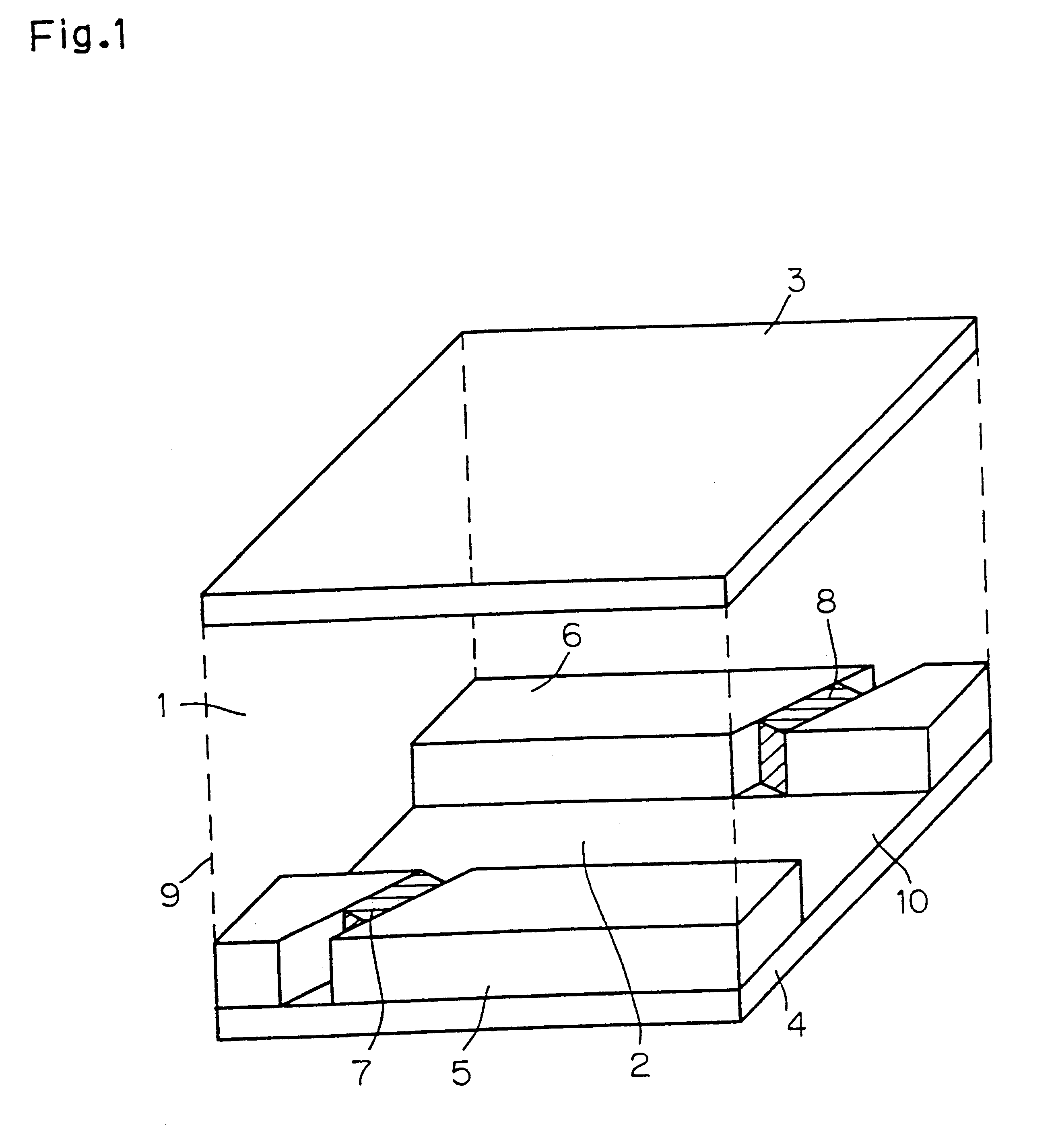
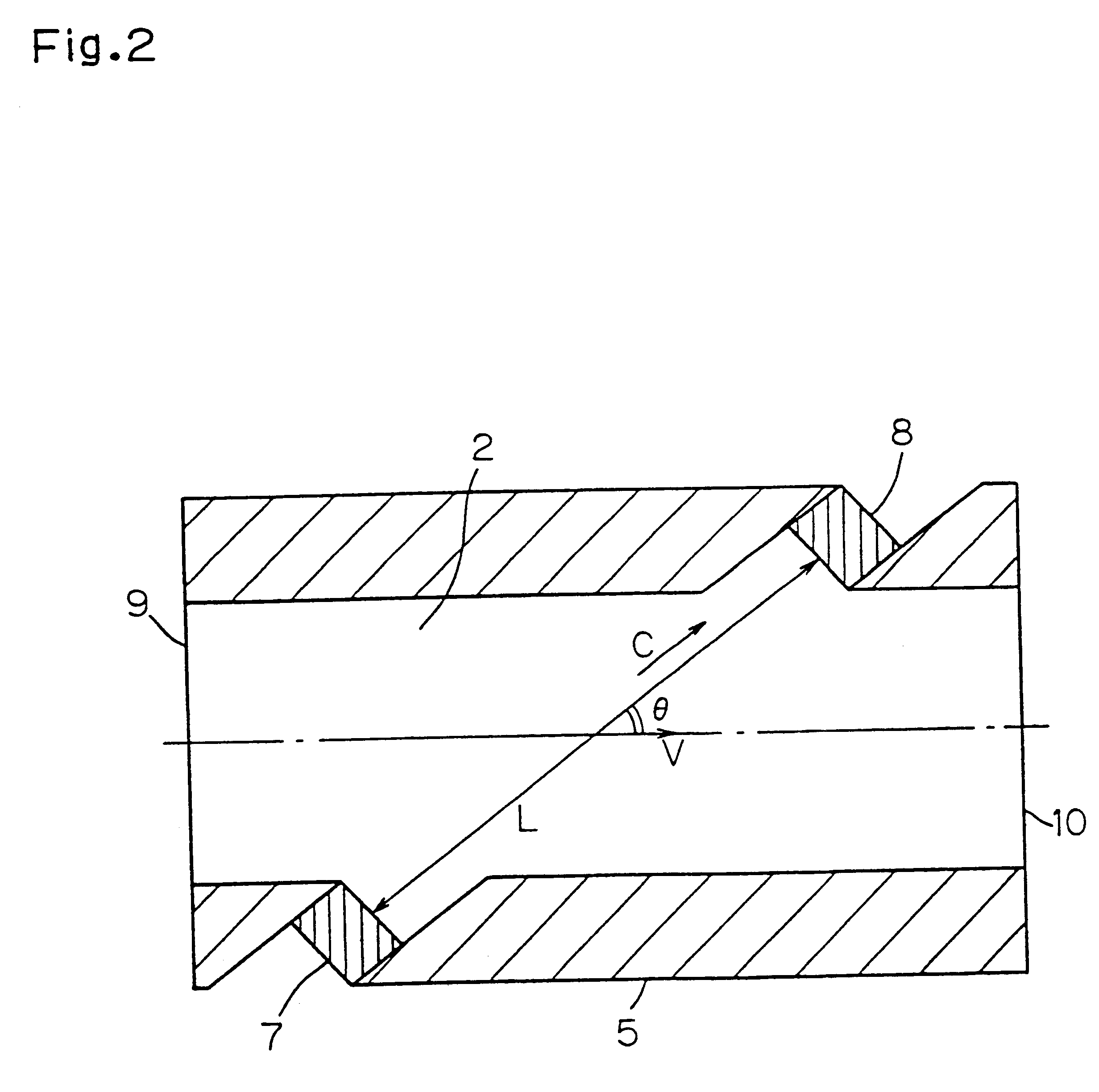
FIG. 1 is a schematic diagram of a flow rate detecting unit of an ultrasonic flowmeter in a first embodiment of the invention. In FIG. 1, reference numeral 1 is air which is a fluid to be measured, 2 is a flow passage of the air 1 flowing at flow velocity V, 3, 4, 5, 6 are top plate, bottom plate, side plate a, side plate B for composing the flow passage 2, 7 is an ultrasonic transducer A disposed on the side plate A 5, 8 is an ultrasonic transducer B disposed on the side plate B 6, 9 is an inlet side of the flow passage 2, and 10 is an outlet side of the flow passage 2. FIG. 2 is a top view of FIG. 1, showing the configuration of ultrasonic transducer.

An example of manufacturing method of the flow rate detecting unit of thus constituted ultrasonic flowmeter is briefly described below while referring to FIG. 1 and FIG. 2. Materials used in the top plate 3, bottom plate 4, side plate A 5, side plate B 6 for composing the flow passage 2 are flat plates of any material ...

embodiment 2

(2) Embodiment 2

A second embodiment of the invention is described below while referring to the drawing.

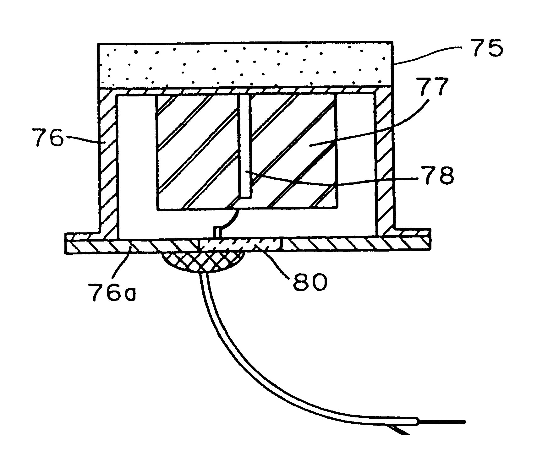
FIG. 4 is a schematic structural diagram of an ultrasonic transducer used in an ultrasonic flow meter in the second embodiment of the invention. In FIG. 4, reference numeral 18 is a matching layer, 19 is a backing layer, and 20 is a lead wire, and the constitution is so far same as in FIG. 3. What differs from the constitution in FIG. 3 is as follows: in the piezoelectric plate 15 being 0.6 or more in either the ratio of the longitudinal side to the thickness or the ratio of the width to the thickness, a groove 16 in a depth of 90% or more and less than 100% of thickness is provided to divide the piezoelectric plate 15 into two sections so that the ratio of the longitudinal side to the thickness in the shape of the electrode surface is 0.6 or less and that the ratio of the width to the thickness is 0.6 or less, the electrode divided into two sections is electrically connected to a ...


PUM


Abstract

An ultrasonic flowmeter includes a flow passage and an ultrasonic transducer for measuring the flow rate in the flow passage wherein the ultrasonic transducer is equipped with a piezoelectric material having electrodes on the opposed surfaces thereof, one of which is used as an ultrasonic wave transmitting/receiving surface and faces the flow passage. The lengths of the sides of the transmitting/receiving surface is so determined that the vibration in the electrode direction is the main mode, preferably that the ratio of the lengths of the sides of the transmission/reception surface to the thickness is not greater than 0.8. Consequently, because the flow meter uses the thickness longitudinal vibration of the piezoelectric material as the main mode, the ultrasonic transducer has a high sensitivity, a high speed response and a small size and the ultrasonic flow meter has a high accuracy and is compact.

Description

THIS APPLICATION IS A U.S. NATIONAL PHASE APPLICATION OF PCT INTERNATIONAL APPLICATION PCT / JP96 / 03629.The present invention relates to an ultrasonic flowmeter for measuring the flow rate of a fluid and an ultrasonic transducer used therein, by disposing a pair of ultrasonic transducer sets at the upstream side and downstream side of the fluid each, transmitting an ultrasonic wave from one ultrasonic transducer, and receiving by other ultrasonic transducer.Traditionally the technology for measuring the flow rate of a fluid flowing in a piping by using ultrasonic wave has been developed. An ultrasonic flowmeter is known in a constitution as disclosed as "Trial fabrication of ultrasonic flow meter for gas" in Measurement Research Report Vol. 26, No. 1, pp. 1-6, Japan.Conventional ultrasonic flowmeter and ultrasonic transducer are described below.FIG. 20 shows a constitution of a conventional ultrasonic flowmeter, and FIG. 21 shows a constitution of a conventional ultrasonic transducer ...

Claims


Application Information

Patent Timeline
Patent Type & Authority Patents(United States)
IPC IPC(8): G01F1/66
CPCG01F1/662G01F1/66
Inventor ADACHI, AKIHISAWATANABE, ATSUSHISATO, TOSHIHARUAZUMA, NAOKOHASHIMOTO, MASAHIKO
Owner PANASONIC CORP
Why Eureka
Try Eureka