Method, system and program for topographical interfacing

a topographical interface and data processing system technology, applied in the field of interface devices, can solve the problems of limited data entry devices, limited two-dimensional display, and limited three-dimensional world, and achieve the effects of reducing the number of data entry devices

Inactive Publication Date: 2003-01-21
IBM CORP
View PDF5 Cites 161 Cited by
  • Summary
  • Abstract
  • Description
  • Claims
  • Application Information

AI Technical Summary

Problems solved by technology

These display devices may be utilized to convey a wide range of information, however are typically limited to two-dimensional display.
While graphical achievements have been made in order to display a virtual three-dimensional object, the three-dimensional world is still limited to two-dimensional visual representation with typical display devices.
Data entry devices, such as the keyboard are limited in that they receive input in relation to fixed control indicia.
More recently developed, a vocal recognition device may be utilized in lieu of a keyboard, however because of privacy and environmental noise considerations, there are limitations on the usability of vocal recognition devices.
Pointing devices, both isotonic and isometric, are limited in that these devices typically only provide visually represented association to a user.
Further, most isometric controllers are limited in that they are only input devices and are not able to provide active force feedback to a user.
The user is thus not able to experience force feedback when manipulating the isometric controller which can be provided when manipulating an isotonic controller, such as a joystick.
The user is therefore missing potentially valuable and interesting force information and assistance in executing tasks in a graphical environment when utilizing a traditional isometric controller.
Additionally, most pointing devices are limited to non-symbolic input whereby the user must switch between pointing devices and data entry devices in order to accomplish tasks.
Constant switching between devices often reduces user efficiency in performing tasks.
However, the sensing system does not provide for detecting the magnitude of force from user input and responding with force feedback.

Method used


Image

  • Method, system and program for topographical interfacing
  • Method, system and program for topographical interfacing
  • Method, system and program for topographical interfacing

Examples


Embodiment Construction

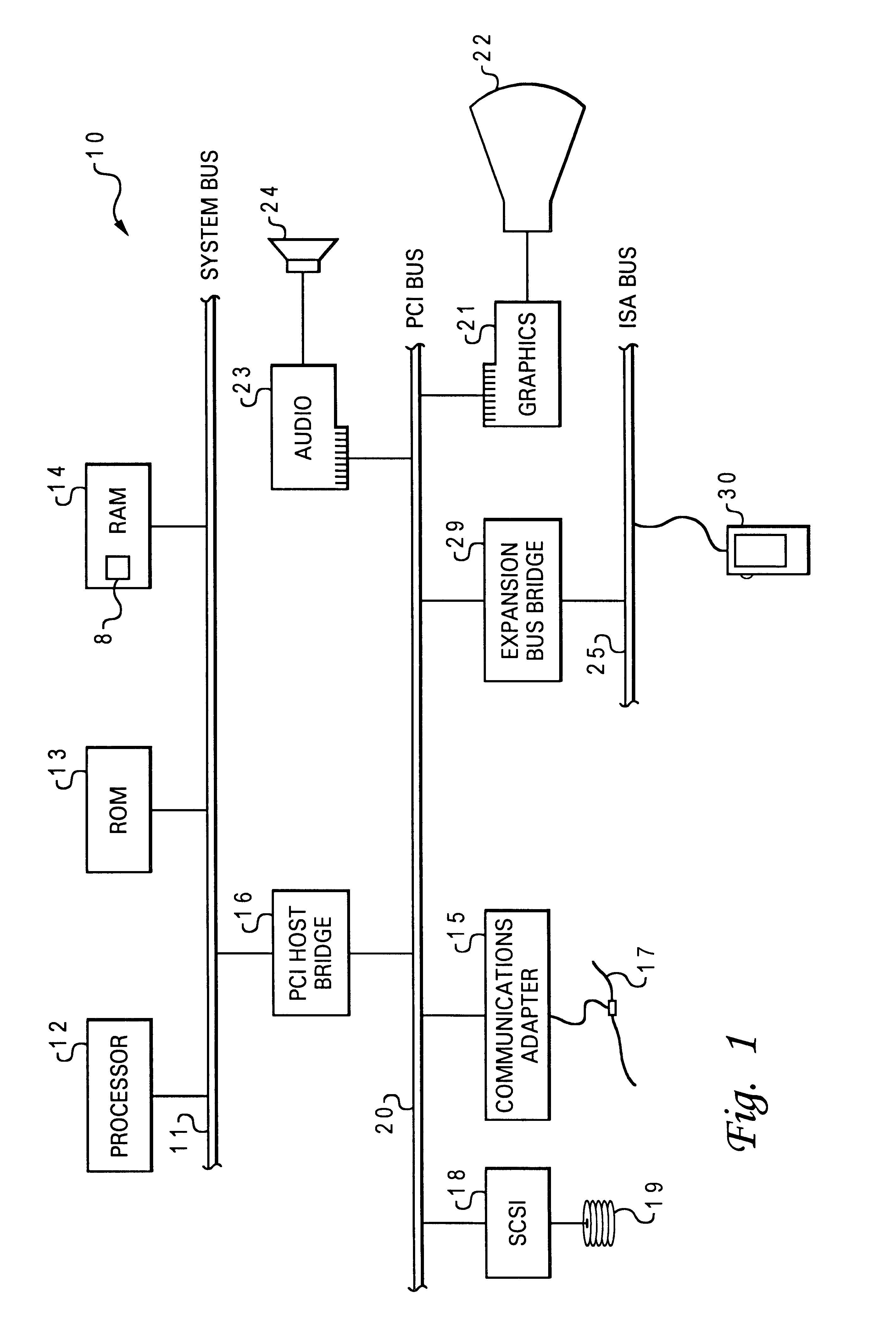
The present invention may be executed in a variety of systems, including a variety of computers under a number of different operating systems. The computer may be, for example, a personal computer, a network computer, a midrange computer or a mainframe computer. In addition, the computer may be a stand-alone system or part of a network such as a local-area network (LAN) or a wide-area network (WAN).

Referring now to the drawings and in particular to FIG. 1, there is depicted a block diagram of a typical computer system that may utilize a preferred embodiment of the present invention. As shown, a processor (CPU) 12, a read-only memory (ROM) 13, and a Random-Access Memory (RAM) 14 are connected to a system bus 11 of a computer system 10. CPU 12, ROM 13, and RAM 14 are also coupled to a PCI local bus 20 of computer system 10 through a PCI host bridge 16. PCI Host Bridge 16 provides a low latency path through which processor 12 may directly access PCI devices mapped anywhere within bus m...


PUM


Abstract

A control surface is enabled that is flexible to provide a tactile-detectable graphical representation of graphical output from a data processing system. Application of external force to the control surface is detected. Closed-loop force feedback through the tactile-detectable graphical representation is controlled, in response to detection of external force applied to the control surface. In addition, adjustment of a view element is detected. The magnification of the graphical output that is represented by the tactile-detectable graphical representation is controlled, in response to detection of adjustment of the view control element.

Description

1. Technical FieldThe present invention relates in general to interface devices, and in particular to an improved topographical interface device for a data processing system. Still more particularly, the present invention relates to a method, system and program for providing a tactile-detectable graphical representation of a graphical output from a data processing system, wherein force feedback is achievable.2. Description of the Prior ArtData processing systems typically rely on at least one if not multiple independent peripheral devices in order to receive inputs and / or transmit outputs to provide human-computer interactions. In general, data processing systems rely on a pointing device and a data entry device for receiving inputs and a display device for outputting data in a visual manner.Presently, typical display devices include, for example, a display monitor, an overhead projection monitor, or other alternate device by which data may be displayed in a visual manner from a dat...

Claims


Application Information

Patent Timeline
Patent Type & Authority Patents(United States)
IPC IPC(8): G09B21/00G06F3/033G06F3/02G06F3/00G06F3/01G06F3/041G06F3/046
CPCG06F3/011G06F3/016G06F3/0213G09B21/004G06F3/0412G06F3/046G06F3/0362G06F2203/014
Inventor COOPER, MICHAELKAMPER, ROBERTPAOLINI, MICHAEL
Owner IBM CORP
Why Eureka
Try Eureka