Disk drive device

a technology of a drive device and a drive body, which is applied in the direction of undesired vibration/sound insulation/absorption, data recording, instruments, etc., can solve the problems of increased vibration, unbalanced weight, and increased vibration, and achieve the effect of suppressing vibration and low vibration

Inactive Publication Date: 2003-01-21
HITACHI LTD
View PDF18 Cites 19 Cited by
  • Summary
  • Abstract
  • Description
  • Claims
  • Application Information

AI Technical Summary

Benefits of technology

An object of the present invention is to provide a low vibration mechanism for rotation driving systems, which tend to be operated at high speed, and for suppressing vibrations produced at the time of low speed rotation and ensuring reliability in a disk drive device having a built-in unbalance correcting mechanism, such as CD-ROM drives of high data transfer.
In order to achieve the above object, the invention provides a disk drive device comprising a rotation driving mechanism for rotating a disk-shaped storage medium having an information recording surface, a head for at least reading an information on the storage medium, support members holding a base plate, on which the rotation driving mechanism and the head are mounted, correcting members for correcting unbalance of rotatingly movable parts including the storage medium, an unbalance correcting mechanism having a rolling groove in the rotation driving mechanism, and auxiliary member or members provided in the rolling groove for increasing or reducing rolling and sliding resistances of the correcting members on surfaces in the rolling groove, the auxiliary member or members making rolling and sliding resistances of the correcting members different between an outer side surface of the rolling groove, which serves as a track surface for the correcting members, and a bottom surface of the rolling groove. The rolling and sliding resistances of the correcting members on the bottom surface of the rolling groove are made larger than the rolling and sliding resistances of the correcting members on the outer side surface of the rolling groove.

Problems solved by technology

In particular, data transfer has recently been effected at high speed and so attended by high speed rotation of a disk, which involves vibrations due to unbalance of the above-mentioned rotating system.
A problem associated with high speed rotation of a spindle motor is an increase in vibrations due to unbalance of a rotating system.
Further, weight unbalance is caused due to printing of characters and patterns on a disk or to a label or the like applied on the disk for identification of the disk.
When a disk with such unbalance is rotated, unbalance vibration occurs due to inconsistency between a center of gravity of and an axis of rotation of a rotating system.
As seen from the formula (1), unbalance vibration is in proportion to the square of a rotational frequency, so that high speed rotation sharply increases the unbalance vibration.
The unbalance vibration not only causes vibration of an optical pickup system to impede read / write of signals, but also causes generation of noises and vibration of a system itself, to which the device is mounted, thus remarkably lowering reliability of the system itself.
In a 24.times. speed or 32.times. speed CD-ROM drive, for example, a disk is rotated at 5,000 to 7,000 rpm, which raises a problem of disk unbalance vibration as mentioned above.
With this arrangement, a range of rotational frequency adequately exceeding the resonance point of elastic members supporting a driving system is used for operation, but forces acting on the correcting bodies become unstable around the resonance point such that, when the correcting bodies begin rolling within the groove, they will never stop rolling, and so vibrations caused due to rolling of the correcting bodies become problematic.
Further, in the case where the disk rotation speed is low and the device is set vertical, dead loads on the respective correcting bodies are greater than centrifugal forces generated by rotation, resulting in a phenomenon that the correcting bodies fail to rise along the annular groove and behave violently in a lower part of the groove.

Method used


Image

  • Disk drive device
  • Disk drive device
  • Disk drive device

Examples


Embodiment Construction

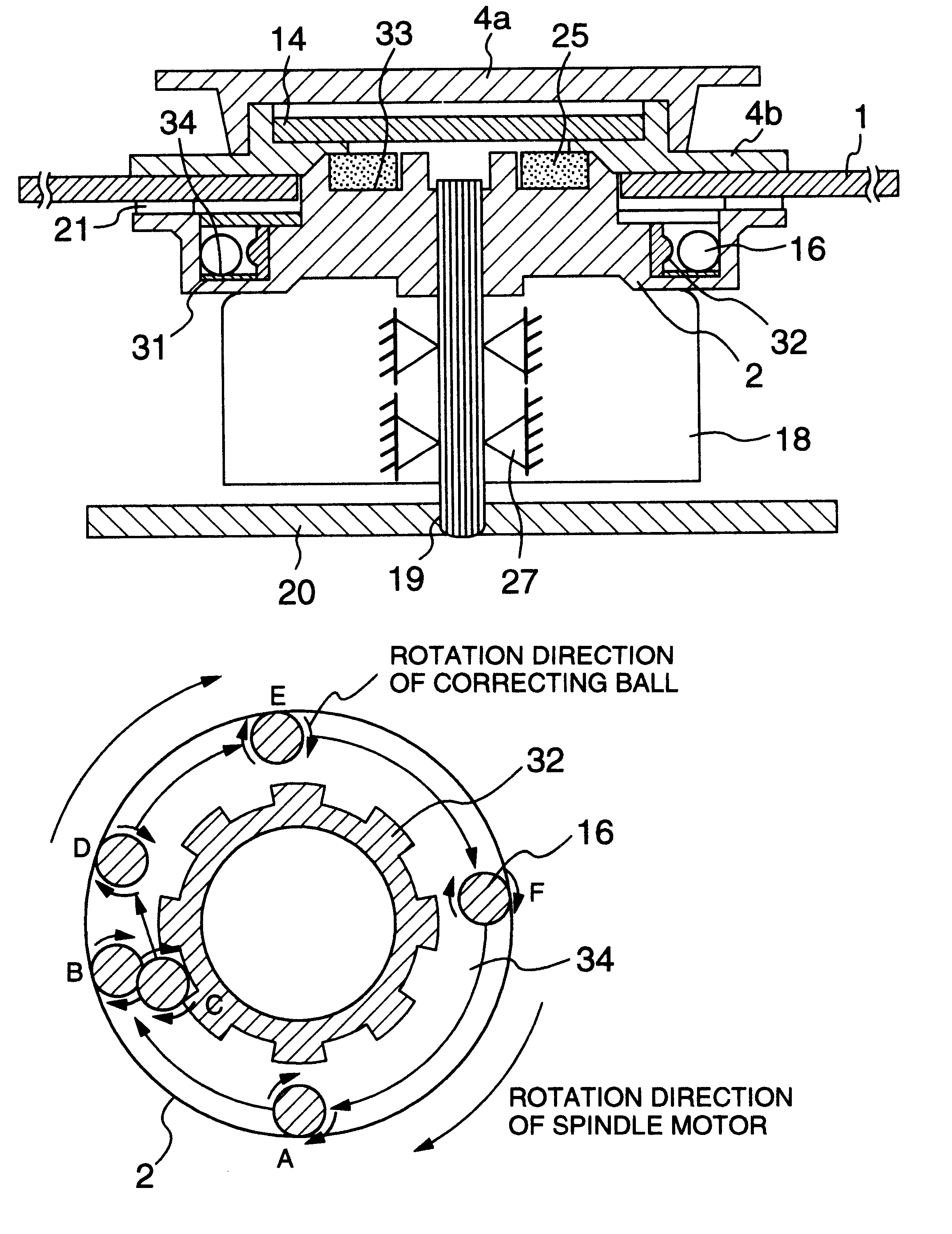
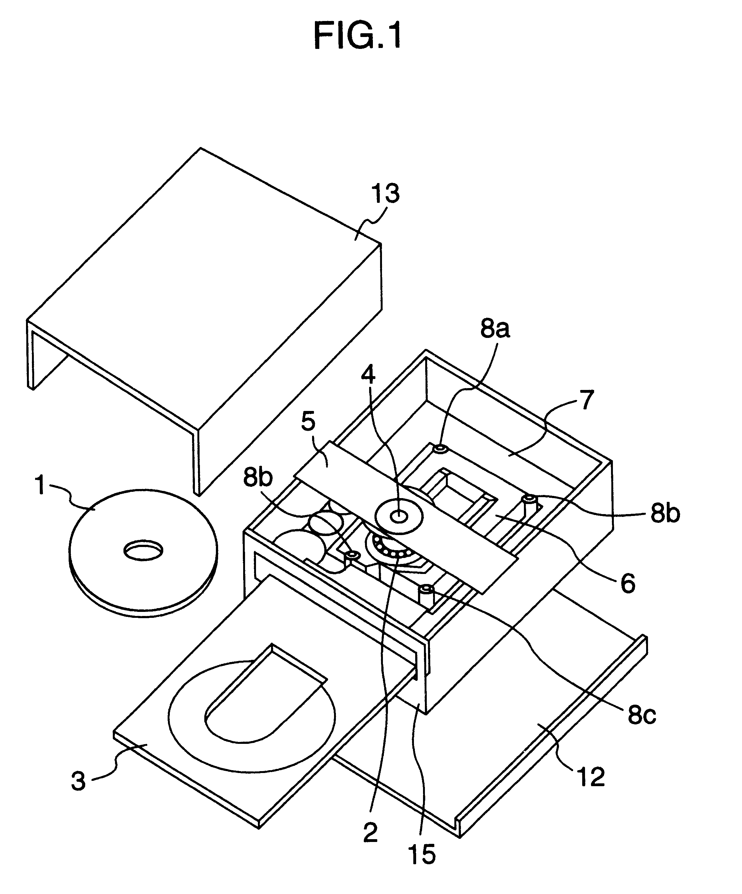
FIG. 1 shows an appearance of a disk (CD-ROM) drive device according to an embodiment of the present invention.

An optical disk unit acts such that a disk tray 3, which places thereon a disk 1, is caused by a disk loading mechanism (not shown) to project from an opening formed in a front panel 15 of the disk unit so that the disk 1 being a storage medium is charged into (or ejected from) the disk unit. In this state, the disk 1 is placed on the disk tray 3 thus projected. Then, the disk loading mechanism causes the disk tray 3 to be charged into the disk unit together with the disk 1.

Thereafter, the disk 1 is fixed on a turntable 2 by magnetic attraction generated from a disk damper 4, which is mounted on a clamper holder 5 above the turntable 2 serving as a disk holding base provided on a spindle motor constituting a disk driving mechanism. Subsequently, the spindle motor starts rotating the disk 1 at the prescribed rotational speed so that data recorded on the disk 1 is reproduced ...


PUM

PropertyMeasurementUnit
elasticaaaaaaaaaa
speedaaaaaaaaaa
volumeaaaaaaaaaa

Abstract

Disk storage devices have exhibited an increase in rotational vibrations which attend high speed rotation due to weight unbalance of a disk. Accordingly, an unbalance correcting mechanism, provided with correcting balls to correct the aforesaid unbalance, meets a problem that the correcting balls are made unstable at the time of low speed rotation to generate vibrations and noises. A disk drive device is provided with an unbalance correcting mechanism comprising an annular-shaped groove provided in a turntable on a spindle motor and a plurality of correcting balls received in the groove, and in which a sliding resistance member is provided on a bottom surface of the annular-shaped groove to suppress a sliding resistance of the correcting balls on the sliding resistance member, and a correcting ball motion auxiliary member is provided on an inner peripheral side wall of the groove (toward an axis of rotation).

Description

The present invention relates to a disk drive device for rotating a disk-shaped replaceable storage medium at high speed for reproduction of or recording and reproduction of information, and more specifically to a disk drive device suitable for high speed rotation of disks including CD-ROM, DVD-ROM, DVD-RAM, MO, removable HDD and so on.In conventional CD-ROM drive devices, causes for lowering positional accuracy are classified into two kinds: (1) vibrations caused by a spindle driving system and a pickup driving system, and (2) disturbing vibrations transmitted from the outside. Typical examples of the cause of the kind (1) includes vibrations due to unbalance of a rotating system, electromagnetic vibrations of a motor, and driving reaction force of the pickup driving system. One of the most important subjects in designing such devices is to ensure a required positioning accuracy despite of such causes for lowering positioning accuracy.In particular, data transfer has recently been ...

Claims


Application Information

Patent Timeline
Patent Type & Authority Patents(United States)
IPC IPC(8): G11B33/08G11B17/028G11B19/20
CPCG11B17/028G11B33/08G11B17/0285G11B19/2018G11B19/2027
Inventor YAMAUCHI, YOSHIAKIMIKI, HISAHIROMORI, SHIGEKIYOSHIDA, SHINOBUKOUNO, TAKASHISATO, YOSHIHIROKIMURA, KUNIYUKI
Owner HITACHI LTD
Why Eureka
Try Eureka