Production of patterned coated abrasive surfaces

a technology of patterned coating and abrasives, which is applied in the direction of grinding devices, manufacturing tools, coatings, etc., can solve the problems of not necessarily crisp definition of each element of the pattern, and achieve the effect of less intense local variation of the field, less clear definition of the desired pattern, and enhanced deposition

Inactive Publication Date: 2003-01-28
MORTON CO
View PDF3 Cites 31 Cited by
  • Summary
  • Abstract
  • Description
  • Claims
  • Application Information

AI Technical Summary

Benefits of technology

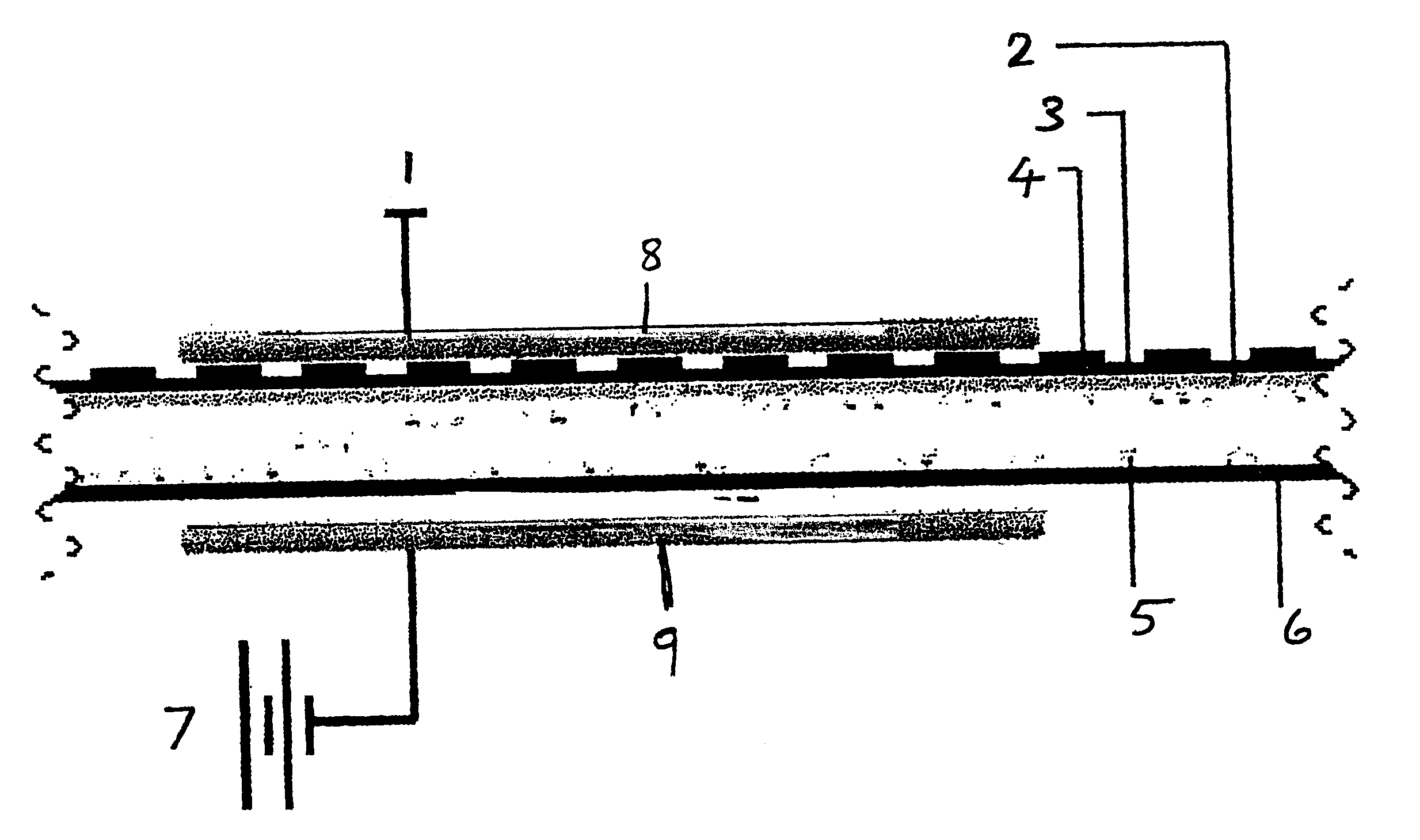
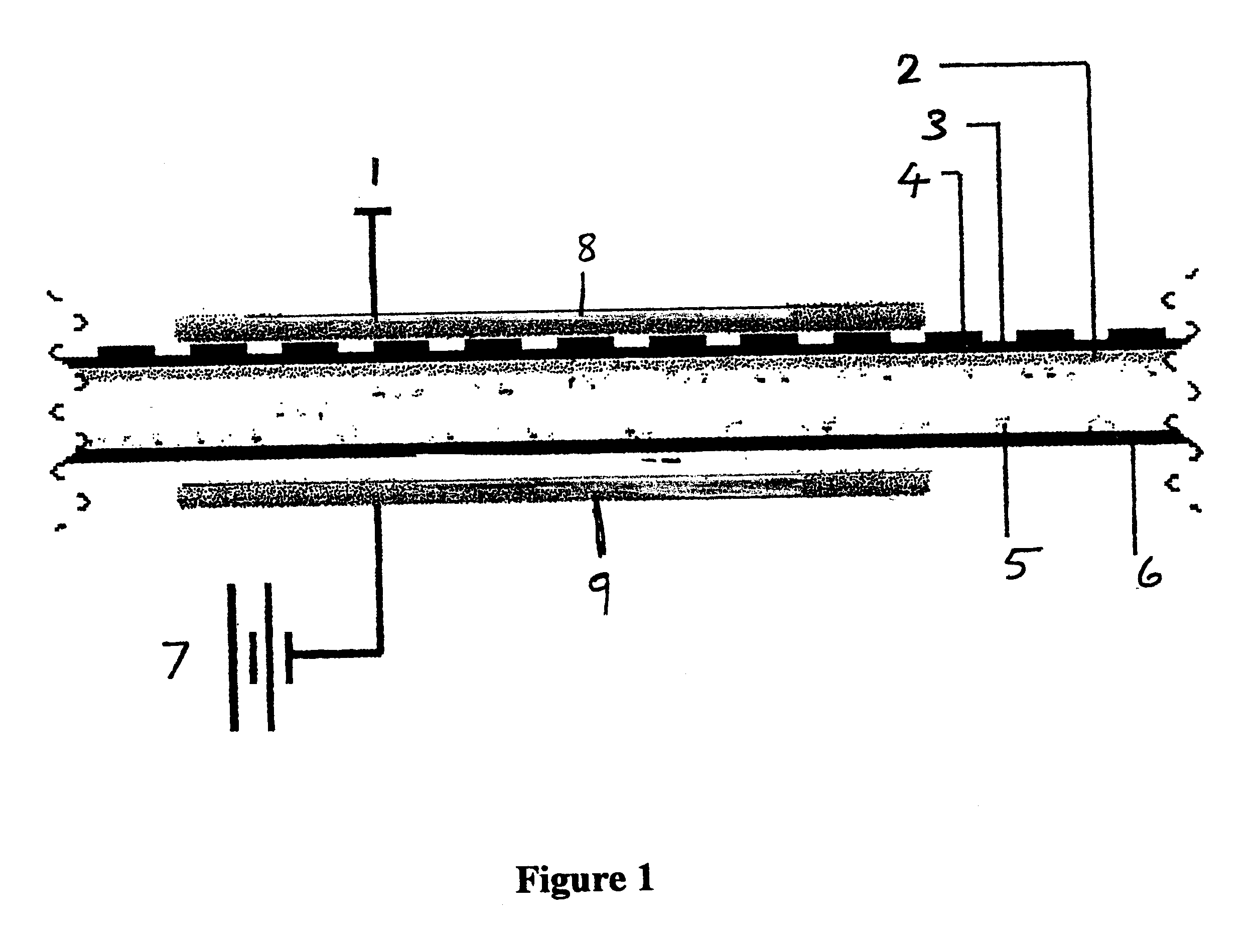
The variations can be brought about in a number of ways, each of which can provide significant advantages for different applications. The field can for example be essentially uniform between conventional electrodes but be locally intensified by the passage of a treated deposition substrate between the electrodes. Thus for example a backing having first and second major surfaces with a maker coat applied to the first major surface and a pattern printed on the second major surface in a conductive ink will, as it passes between the electrodes, locally intensify the field and therefore the deposition on the first major surface opposite the printed areas. If the field strength is adjusted such that, in the absence of the local intensification, it is insufficient to bring about significant deposition of the grain on the substrate, grain will be deposited in a pattern that corresponds to the pattern printed on the reverse side of the film. This pattern can be as simple as a series of dots or stripes or perhaps more complex patterns as desired. Sometimes it may be desirable to print stripes along the lateral edges of a sheet to ensure enhanced deposition in an area that is often inadequately provided with abrasive grain when using conventional UP processes. The printing is most frequently applied to the back side of the substrate, that is the side opposite to that on which the abrasive grain is to be deposited. This however is not essential and printing on the side to receive the grain can often have advantages.
This embodiment of the process is particularly effective when the backing is a plastic film or paper rather than a fabric material which may produce a less intense local variation of the field and therefore less clear definition of the desired pattern.
Creating the pattern using conductive ink printing has the great advantage of being extremely versatile and, since it employs conventional UP deposition equipment, can be used in conjunction with a suitable printing station to generate any desired pattern without extensive modification of the UP grain deposition equipment between runs of different patterns.
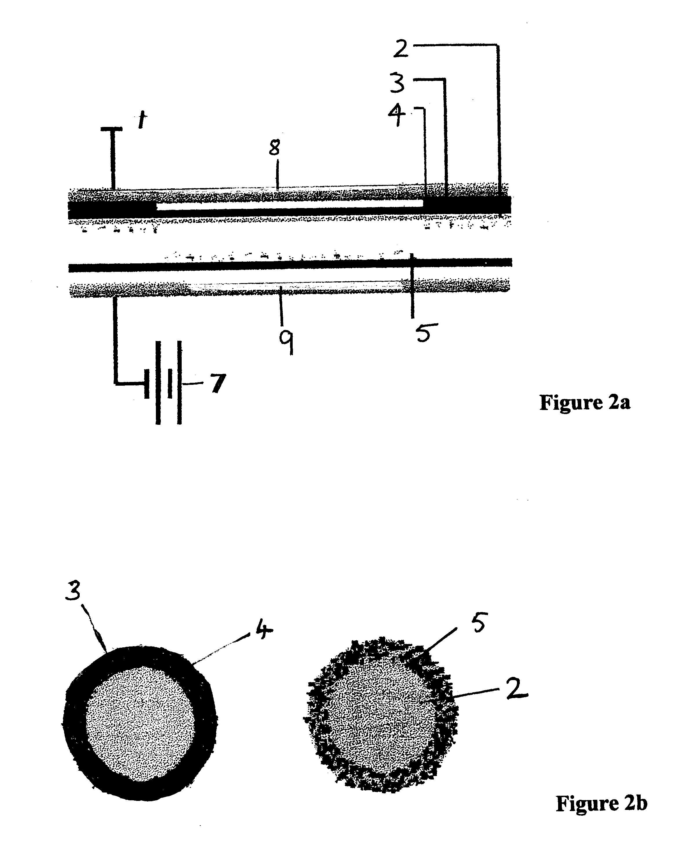
An alternative method of varying the intensity of the electrostatic field is through the use of shaped electrodes. In its simplest embodiment, the ground electrode is ring-shaped. If this is to be used in a continuous process, the field will need to be generated in interrupted fashion and coordinated with passage of the backing between the electrodes. It is however possible to produce individual discs that have been pre-cut and positioned on a conveyor passing between the electrodes providing the timing of deposition can be accurately controlled to correspond with the position of the disc.
Patterned electrodes can be readily fashioned by patterned printing using conductive ink on an insulating substrate such as a polyester or polyvinylidenefluoride film. Alternatively a metal-coated insulating film can be etched to give the desired pattern. Other techniques well-known in the art can also be employed to make patterned electrodes.

Problems solved by technology

The definition of each element of the pattern is not necessarily crisp because electrostatic fields between electrodes are not defined by clear lines of demarcation.

Method used


Image

  • Production of patterned coated abrasive surfaces
  • Production of patterned coated abrasive surfaces
  • Production of patterned coated abrasive surfaces

Examples


example 1

In this Example we illustrate the results of the use of a process according to the invention. The apparatus used is as illustrated in FIG. 3 except that the grounded electrode was a flat electrode in place of the ring electrode illustrated in the drawing. The live ring electrode had an outside diameter of 20.32 cm., a radial width of 4.45 cm. A vulcanized fiber backing material coated with a pressure sensitive adhesive, (used as a substitute for the uncured maker coat that would be used in a commercial operation), was attached to the grounded electrode. The separation between the backing material and the live electrode was 1.11 cm. A tray of abrasive grain was placed between the electrodes adjacent the live electrode which was then connected to a 10-30 kV DC power supply. The pattern of deposition is illustrated by the scanned images presented as FIG. 7 which shows three discs coated in this manner with differing times of deposition. They show a clear pattern of deposition in the pr...


PUM

PropertyMeasurementUnit
diameteraaaaaaaaaa
diameteraaaaaaaaaa
conductiveaaaaaaaaaa

Abstract

An electrostatic abrasive grain upward projection deposition process utilizing opposed electrodes produces a patterned abrasive surface by controlling the local intensity of the field by which the grain is projected on to a substrate.

Description

This invention relates to coated abrasives and specifically to a method or making coated abrasives with a patterned surface.It is well known that there are significant advantages to be obtained from the selective deposition of abrasive materials on a substrate. These may range from the avoidance of wasted grain by non-deposition on the parts of a substrate that do not see active abrasion during conventional use, to the creation of islands of abrasive material that ensure efficient use of the abrasive grain and room for swarf to be carried away during grinding. The present invention provides a very efficient and versatile way of producing patterned coated abrasive surfaces that can be adapted to all manner of coated abrasive applications.In the production of a conventional coated abrasive, a backing is provided with a maker coat, the primary function of which is to bind abrasive grain deposited thereon to the backing. The grain is therefore applied before the maker coat is fully cure...

Claims


Application Information

Patent Timeline
Patent Type & Authority Patents(United States)
IPC IPC(8): B24D18/00B24D11/00B24D3/00
CPCB24D18/00B24D11/005
Inventor MATHISEN, MARK E.SWEI, GWO SHIN
Owner MORTON CO
Why Eureka
Try Eureka