Smart modular receptacle and system

a modular receptacle and modular technology, applied in the direction of coupling device connection, coupling contact member material, coupling protective earth/shielding arrangement, etc., can solve the problems of installation subject to electrical shock, incorrect connection,

Inactive Publication Date: 2003-02-04
CASH JR RONALD G
View PDF36 Cites 39 Cited by
  • Summary
  • Abstract
  • Description
  • Claims
  • Application Information

AI Technical Summary

Benefits of technology

The present invention thus provides a building electrical system wherein the modular electrical receptacles need not be fixed in location relative to corresponding switches or switch controls. The circuitry of the present invention allows any junction box regardless of its location in the system to contain a receptacle that can function as any component of the circuit. Thus, for example, switches can be changed from a single-pole utility to one offering three-way utility by merely changing functionality of the receptacle in electrical communication with a junction box.
In accordance with one embodiment, an electrical system is capable of multi-configurable functionality via use of a low voltage twisted pair actuating and / monitoring circuit that permits central control and monitoring of all such electrical receptacles connected to the system. By providing each electrical junction box with a separate low voltage circuit connection that interfaces with an electrical receptacle connected to each junction box, the circuitry system of the present invention permits the flow of information between receptacles, and accordingly, the control and monitoring of that electrical receptacle. By eliminating any requirement for switches to open or close portions of the electrical system to turn off the switched receptacle, the present invention supports continuity of a communication path between all receptacles of the system, thereby facilitating continuous control and / or monitoring of all receptacles connected to the system, regardless of their locations. Accordingly, individual receptacles may be physically relocated within the system without incurring loss of functionality, monitorability, or controllability. In accordance with another aspect of the invention, the system enables use of reconfigurable processors, having internal logic systems that can control any and / or all of the receptacles in a given electrical system.
In accordance with the present invention, the instant electrical wiring system can also employ an electrical junction box that permits electrical wires from an electrical system of a building to terminate at a set of terminal strips and lugs in a secure area of the junction box rather than directly on an electrical receptacle that is mounted on and connected to the junction box. The improved electrical junction box provides a set of plug-and-play electrical terminals into which electrical receptacles plug directly without any need for relatively permanent wiring. Accordingly, electrical receptacles may be plugged directly into improved electrical junction boxes to form electrical service ports, and such receptacles may easily be relocated to form electrical service ports in any other location within the system.
In accordance with another embodiment of the instant electrical junction box, a low voltage cable is installed through an end panel of a base housing, and terminates into a low voltage connector block, which is removably or fixedly attached to the base housing. A non-conductive low voltage barrier separates the low voltage connector block from the remainder of the junction box, thereby separating all standard voltage cables connected to the conductive terminal strips from the low voltage cables connected to the low voltage connector block. The low voltage connector block is adapted to terminate a low voltage cable and receive a control / monitor pigtail from an electrical receptacle mounted on and electrically connected to the electrical junction box, thereby providing a circuit for an electronic communication path. When a control- or monitor-capable electrical receptacle having a control / monitor pigtail is removably inserted into the junction box, the control / monitor pigtail removably interfaces with the low voltage connector block and completes the circuit. In one described embodiment, the low voltage connector block is enclosed behind the above-described security plate and is therefore contained within the rear portion of the junction box. In this embodiment, the security plate further comprises at least one aperture that substantially corresponds to at least one aperture on the low voltage connector block that is adapted to receive the control / monitor pigtail. Thus, when the security plate encloses the low voltage connector block in a rear portion of the junction box, the control / monitor pigtail can removably and matingly engage the low voltage connector block through the security plate.

Problems solved by technology

Although conventional electrical systems including such junction boxes function at least adequately, they suffer from a variety of limitations.
In the event that power is not shut off while the electrical receptacle is connected to the electrical system, the installer is subject to receiving an electrical shock because the junction box contains a plurality of open wires and connections that are exposed.
Indeed, novice installers, such as homeowners for example attempting to complete the installation of a simple light fixture or ceiling fan, often make such connections incorrectly.
The wires are normally crammed into a junction box relatively tightly, and thus are subject to short-circuiting, with commensurate risks of initiating electrical fires.
Standard electrical practices create additional limitations.
Further, since electrical circuits of a building cannot be tested fully until after walls of the building are erected, electrical connectivity errors or problems related to proper switch control of particular outlets and fixtures are frequent, especially in the case of multi-way switches where more than one switch controls a single fixture or group of fixtures.
These errors are costly and time-consuming to correct, and require that associated portions of interior walls be removed and reconstructed after such electrical errors have been located and repaired.
In addition, current electrical practices provide no standard system or method to permit monitoring, controlling, reconfiguring, or otherwise changing functionality of a particular receptacle, without either directly modifying the receptacle or otherwise acting upon a control mechanism (i.e., a switch or other control device) dedicated to controlling or monitoring the particular receptacle(s), and that is directly wired to the receptacle(s).

Method used


Image

  • Smart modular receptacle and system
  • Smart modular receptacle and system
  • Smart modular receptacle and system

Examples


Embodiment Construction

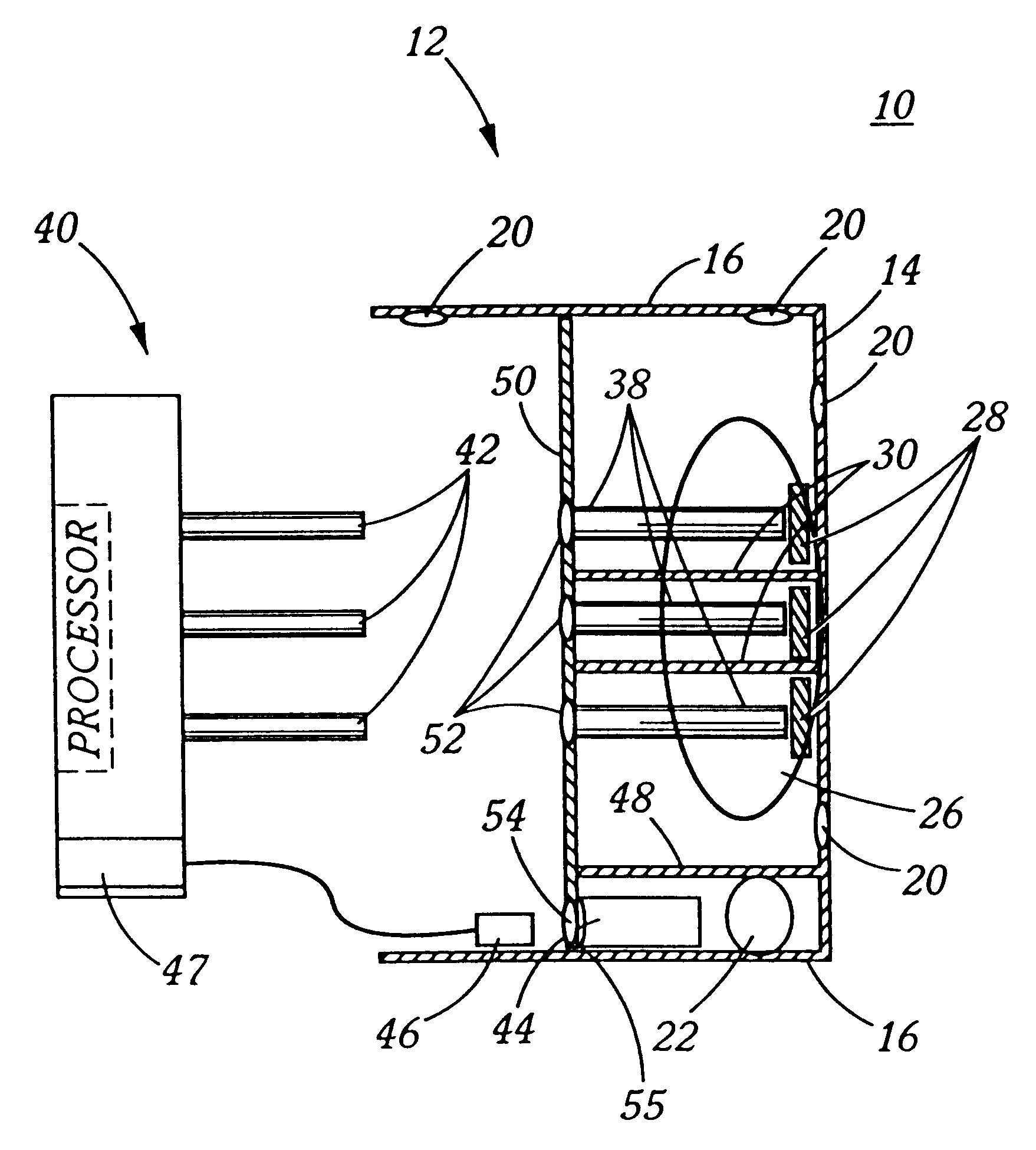
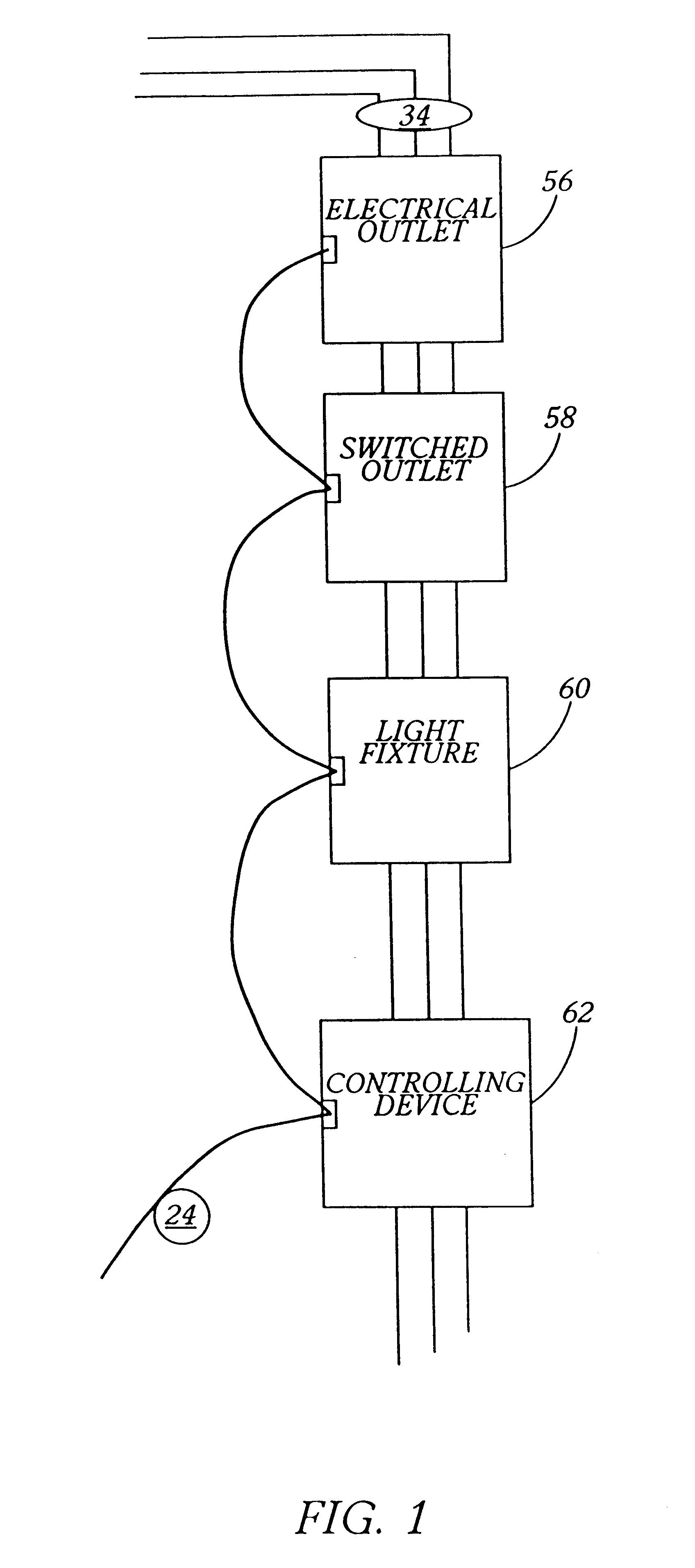
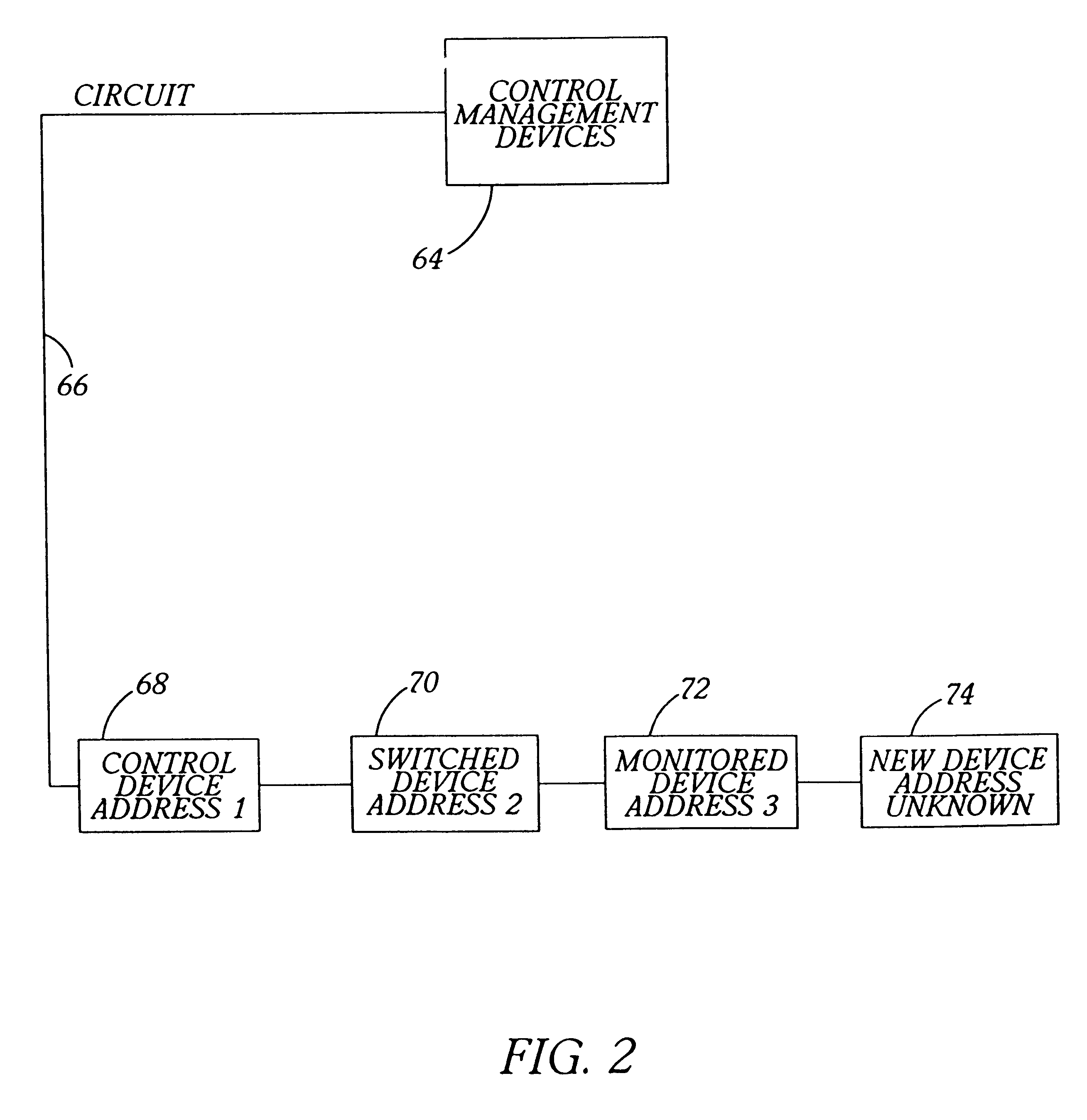
This invention provides the ability to monitor, control, or change the functionality of either a single electrical receptacle or a plurality of electrical receptacles that are connected in series in an electrical system of a building. The invention also enables the location and / or functionality of each monitored, controlled, monitoring, or controlling receptacle to be changed at any time without rewiring. Because the system of the instant invention accomplishes switching on or off within each individual receptacle, it is unnecessary to open the circuit as is required, for example, in a conventionally wired light circuit. As a result, the wiring of the instant system remains available for communication regardless of the on or off status of individual receptacles, and receptacles may communicate with other receptacles in the instant system by sending or receiving signals through the high voltage wiring. Alternatively, receptacles may employ additional low voltage wiring in addition to...


PUM


Abstract

A modular junction box receptacle includes parallel high and low voltage circuitry portions separated by a barrier. A base housing of the receptacle receives a termination block that includes high and low voltage connections to respective high and low voltage portions of the base housing. A housing cover is installed over the base housing and termination block; the cover has an opening for passage thereinto of a face portion of the block. The receptacle accommodates a plug and play unit containing smart circuitry, the unit including high and low voltage circuitry connections for respective high and low voltage portions of the termination block. The unit can act as a variety of interchangeable devices in a smart system that incorporates pluralities of receptacles, including electrical outlets and simple electrical toggle switches, each containing low voltage connections. A plurality of such units may be incorporated in, for example, a household circuitry system.

Description

1. Field of InventionThe present invention relates to improvements in electrical receptacles for use in residential and commercial electrical wiring systems, and particularly to electrical receptacles formed of modular parts for use in electrical wiring systems. More particularly the invention also relates to improved systems and methods for controlling remotely operated electrical devices through electrical wiring of residential and commercial building structures. Finally the invention relates to modular electrical receptacles having capacity for embodying changeable functionality of electrical devices through external programming.2. Description of the Prior ArtThose skilled in the art will appreciate that for safety reasons state and federal building codes require that electrical wiring be fully contained between exterior and interior wall structures of buildings, between floors of buildings and the ceilings beneath the floors, and be otherwise fully contained within rigid enclosu...

Claims


Application Information

Patent Timeline
Patent Type & Authority Patents(United States)
IPC IPC(8): H02G3/00H01R25/00
CPCH02G3/00H01R25/006
Inventor CASH, JR., RONALD G.
Owner CASH JR RONALD G
Why Eureka
Try Eureka