[0016] The present invention thus provides a building electrical
system wherein the modular electrical receptacles need not be fixed in location relative to corresponding switches or switch controls. The circuitry of the present invention allows any junction box regardless of its location in the system to contain a receptacle that can function as any component of the circuit. Thus, for example, switches can be changed from a single-pole utility to one offering three-way utility by merely changing functionality of the receptacle in electrical communication with a junction box.
[0017] In accordance with one aspect of the invention, the processor within a receptacle can be preconfigured (i.e., pre-set or programmed prior to installation) so as to avoid requiring exchange of the entire receptacle within the junction box to change functionality of the electrical unit at the desired location. According to another aspect the processors within the receptacle can be re-configured remotely, after installation, either by use of the building electrical circuitry, or by use of a low voltage independent connection.
[0019] In accordance with one embodiment, an electrical system is capable of multi-configurable functionality via use of a low voltage
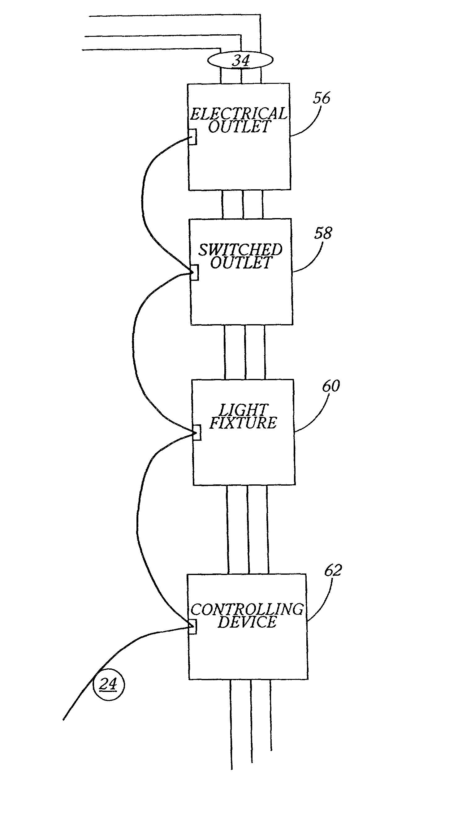
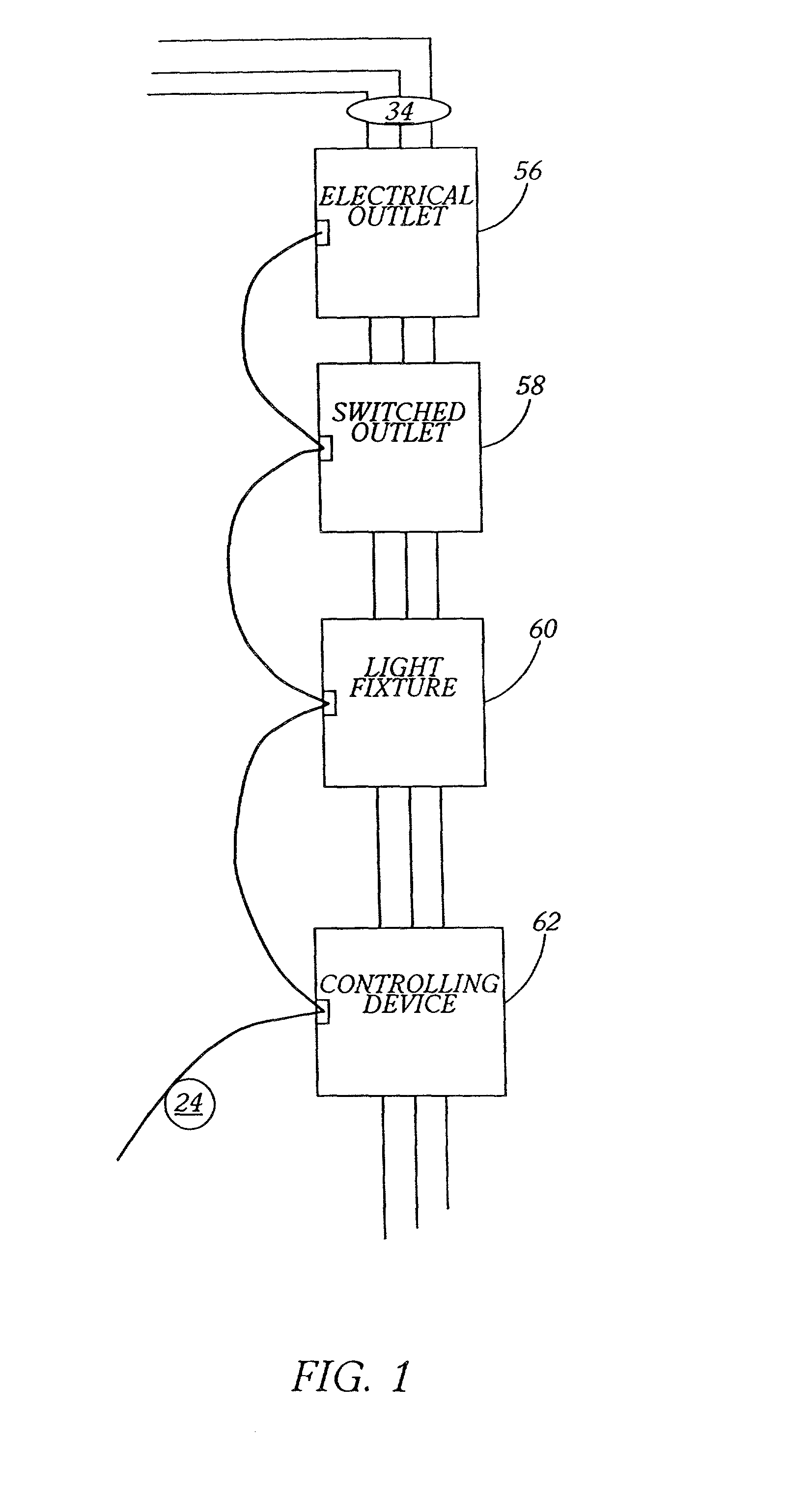
twisted pair actuating and / monitoring circuit that permits central control and monitoring of all such electrical receptacles connected to the system. By providing each
electrical junction box with a separate low voltage circuit connection that interfaces with an electrical receptacle connected to each junction box, the circuitry system of the present invention permits the flow of information between receptacles, and accordingly, the control and monitoring of that electrical receptacle. By eliminating any requirement for switches to open or close portions of the electrical system to turn off the switched receptacle, the present invention supports continuity of a communication path between all receptacles of the system, thereby facilitating continuous control and / or monitoring of all receptacles connected to the system, regardless of their locations. Accordingly, individual receptacles may be physically relocated within the system without incurring loss of functionality, monitorability, or
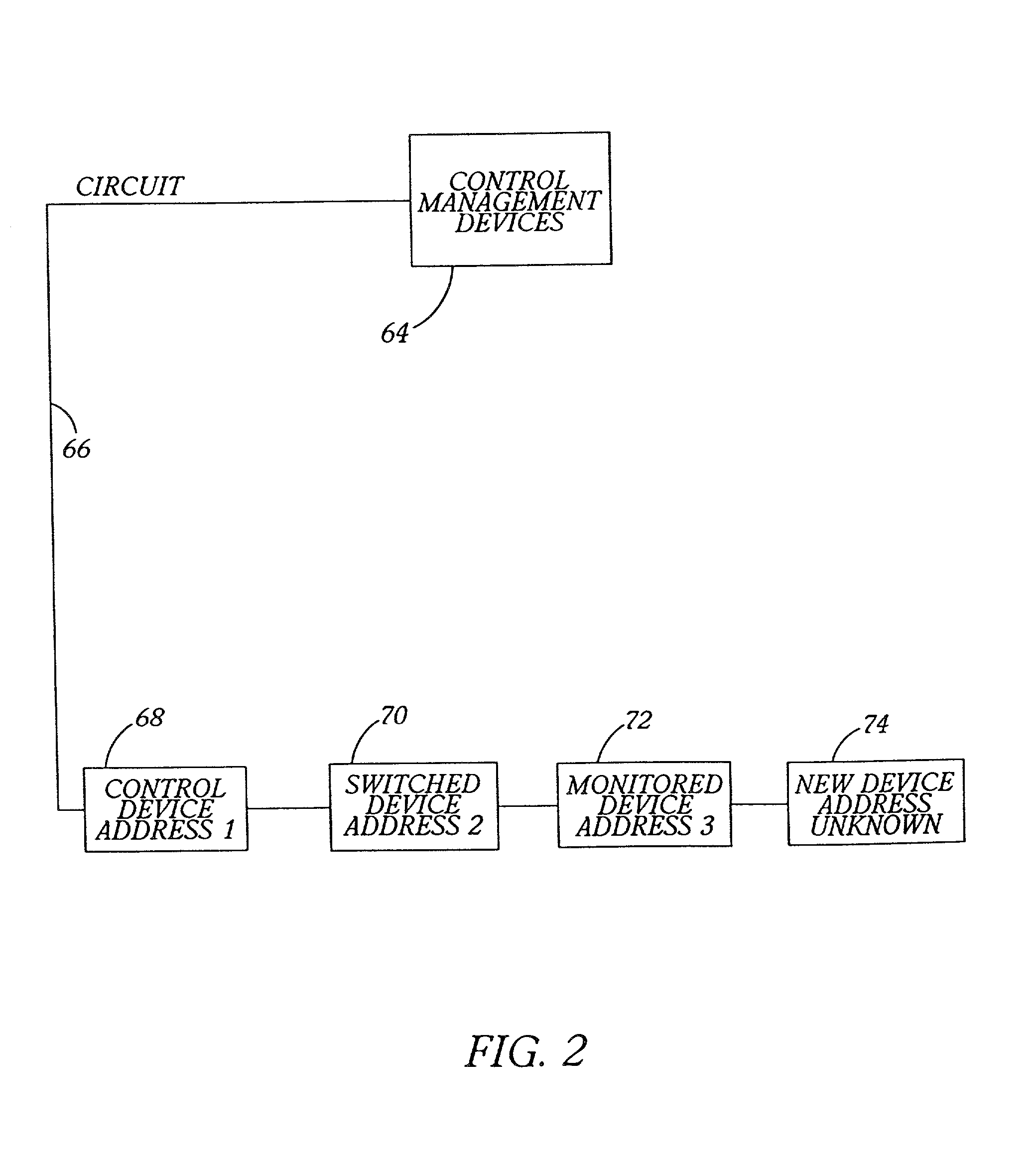
controllability. In accordance with another aspect of the invention, the system enables use of re-configurable processors, having
internal logic systems that can control any and / or all of the receptacles in a given electrical system.
[0021] In accordance with the present invention, the instant electrical wiring system can also employ an
electrical junction box that permits electrical wires from an electrical system of a building to terminate at a set of terminal strips and lugs in a secure area of the junction box rather than directly on an electrical receptacle that is mounted on and connected to the junction box. The improved
electrical junction box provides a set of plug-and-play electrical terminals into which electrical receptacles plug directly without any need for relatively permanent wiring. Accordingly, electrical receptacles may be plugged directly into improved electrical junction boxes to form electrical service ports, and such receptacles may easily be relocated to form electrical service ports in any other location within the system.
[0024] In accordance with another embodiment of the instant electrical junction box, a low voltage cable is installed through an end panel of a base housing, and terminates into a low voltage connector block, which is removably or fixedly attached to the base housing. A non-conductive low voltage barrier separates the low voltage connector block from the remainder of the junction box, thereby separating all standard voltage cables connected to the conductive terminal strips from the low voltage cables connected to the low voltage connector block. The low voltage connector block is adapted to terminate a low voltage cable and receive a control / monitor
pigtail from an electrical receptacle mounted on and electrically connected to the electrical junction box, thereby providing a circuit for an
electronic communication path. When a control- or monitor-capable electrical receptacle having a control / monitor
pigtail is removably inserted into the junction box, the control / monitor
pigtail removably interfaces with the low voltage connector block and completes the circuit. In one described embodiment, the low voltage connector block is enclosed behind the above-described security plate and is therefore contained within the rear portion of the junction box. In this embodiment, the security plate further comprises at least one aperture that substantially corresponds to at least one aperture on the low voltage connector block that is adapted to receive the control / monitor pigtail. Thus, when the security plate encloses the low voltage connector block in a rear portion of the junction box, the control / monitor pigtail can removably and matingly engage the low voltage connector block through the security plate.

