Coupling device

a coupling device and coupling plate technology, applied in the direction of mechanical actuated clutches, friction clutches, friction clutches, etc., can solve the problems of increasing the thickness of the friction plate, increasing the axial dimension of the clutch, and difficult control of slippage, so as to improve the cooling effect of the coupling device and improve the effect of cooling

Inactive Publication Date: 2008-12-18
AISIN AW CO LTD
View PDF13 Cites 13 Cited by
  • Summary
  • Abstract
  • Description
  • Claims
  • Application Information

AI Technical Summary

Benefits of technology

[0012]Accordingly, the cooling oil is fed to both the outer circumferential side and the inner circumferential side of the multi-plate/disc clutch. Consequently, compared to structure in which the cooling oil is fed to only one of the first oil space and the second oil space, temperatures at both the outer and the inner circumferential sides of the clutch can be reduced, and thus, the cooling of the coupling device is further improved.
[0013]In addition, the coupling device of the present invention includes a hydraulic actuator which presses the outer and the inner friction plates together in an axial direction with a piston member, wherein the piston member has oil through holes serving as at least a portion of the bypass oil passage. Accordingly, the bypass oil passage can be formed with a simple configuration merely by providing oil through holes in the piston member.
[0014]In addition, the coupling device according to the present invention preferably has, in the hub member, oil through holes forming at least a portion of the bypass oil passage. Accordingly, the bypass oil passage can be formed with a simple configuration merely by

Problems solved by technology

JP-A-2004-308894, the notches in the friction plates create a problem of a lack of strength due to stress concentration in the supporting portion to which the friction pad is attached, and therefore, the thickness of the friction plate must be increased to ensure the requisite strength.
However, the solution of an increase in plate thickness, in turn, creates a problem by an increase in the a

Method used


Image

  • Coupling device
  • Coupling device
  • Coupling device

Examples


Embodiment Construction

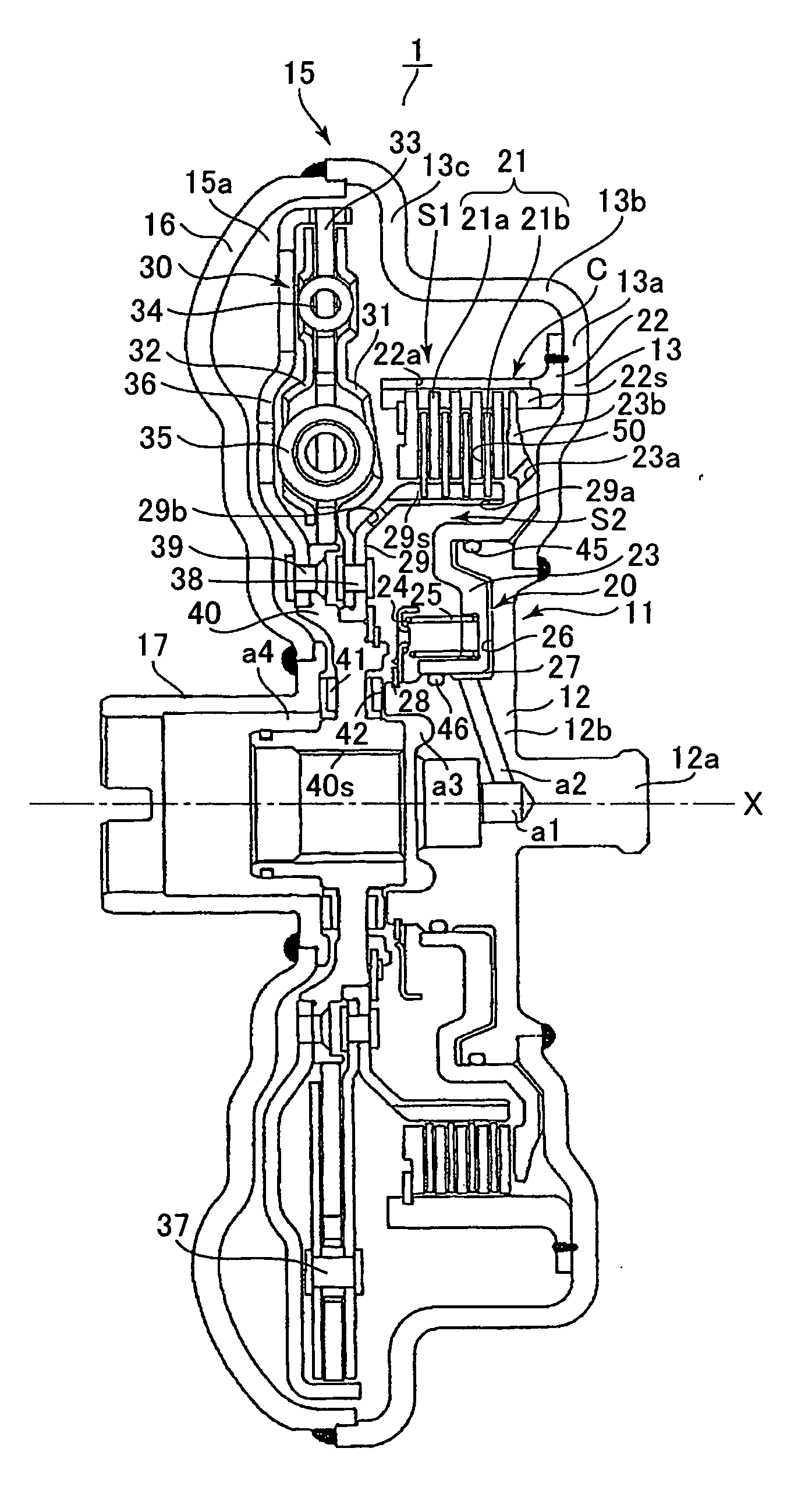
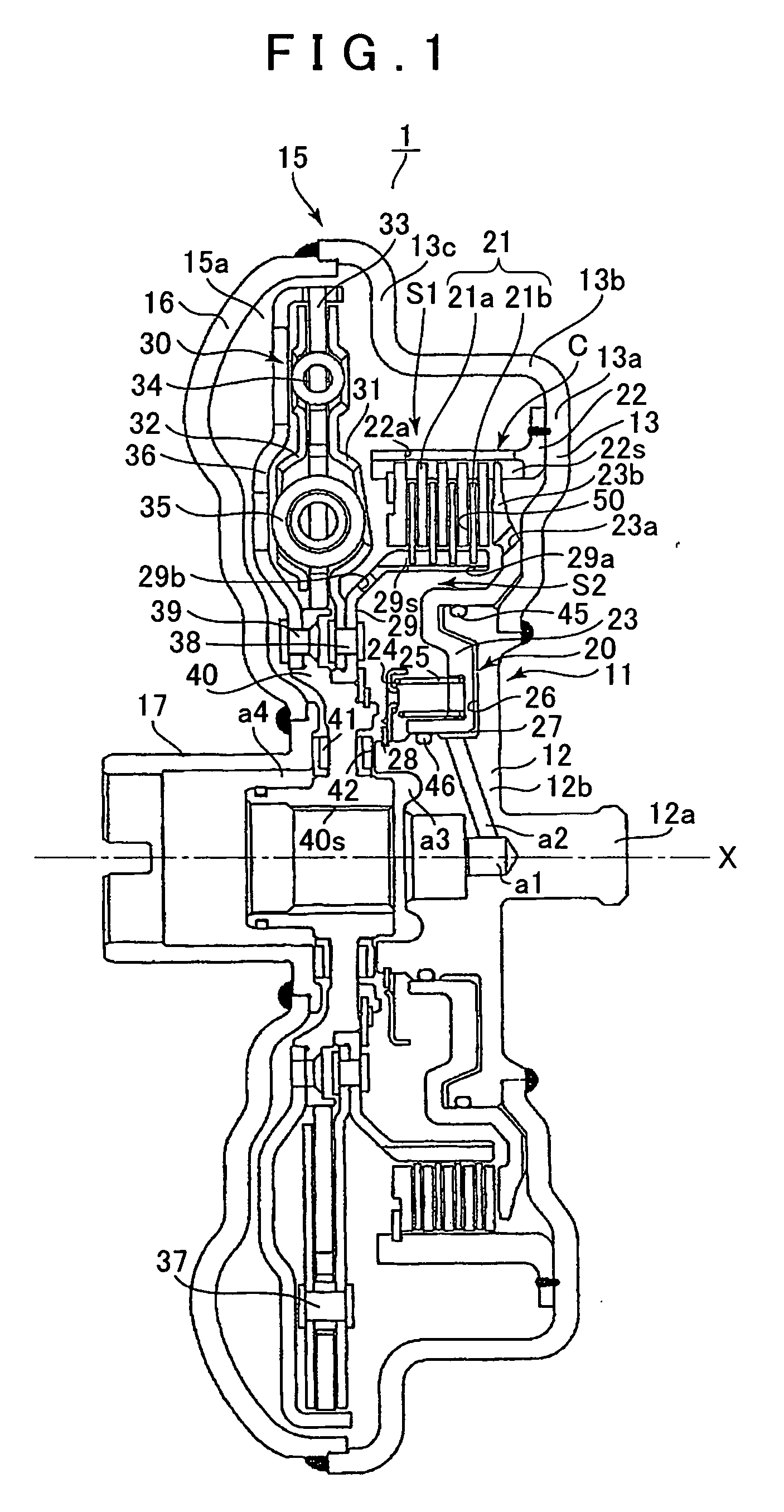
[0020]An embodiment according to the present invention will be described below with reference to FIGS. 1 and 2. It should be noted that, in describing the coupling device 1 shown in FIG. 1, it is assumed that the coupling device is longitudinally mounted in an FR (front-engine rear-drive) type vehicle, and that the right side in the drawing is called “front side” and the left side is called “back side” for the purpose of convenience in description. However, the present invention is not so limited and the coupling device may be laterally mounted, for example, in an FF (front-engine front-drive) type vehicle. In other words the coupling device of the present invention may be mounted in any type of vehicle drive train.

[0021]The coupling device 1 constitutes an automatic transmission when combined with, for example, an automatic speed change mechanism and a hydraulic control unit, and, as shown in FIG. 1, the coupling device 1 includes an input member 11 connected to an output shaft (cr...


PUM


Abstract

Cooling oil is fed to a second oil space formed on the inner circumferential side of a hub member, and is also fed through a bypass oil passage to a first oil space formed on the outer circumferential side of a drum member. When the friction plates rotate, with grooves in the friction pads attached to the inner friction plates, the cooling oil flows by inertial force through oil holes in the hub member and through oil holes of the drum member, from the first oil space to the second oil space, and from the second oil space to the first oil space, respectively, through the friction plates. Accordingly, the flow of the cooling oil to the friction plates is improved without notches, etc. in the outer friction plates or in the inner friction plates, resulting in an improvement in cooling of the coupling device.

Description

INCORPORATION BY REFERENCE[0001]The disclosure of Japanese Patent Application No. JP2007-160459 filed on Jun. 18, 2007 including the specification, drawings and abstract is incorporated herein by reference in its entirety.BACKGROUND OF THE INVENTION[0002]1. Field of the Invention[0003]The present invention relates to a coupling device, preferably for use in a vehicle automatic transmission, and, more specifically, to a coupling device in the form of a multi-plate / disc clutch which is slip-controlled and oil cooled.[0004]2. Description of the Related Art[0005]In a vehicle equipped with an automatic transmission, as well as an internal combustion engine as a drive source, when the engine is first started the automatic speed change mechanism and the drive wheels are not rotating although the engine is rotating. Accordingly, a device is required to transmit driving force while minimizing shock due to connection of the non-rotating wheels with the rotating engine. While hydraulic power t...

Claims


Application Information

Patent Timeline
IPC IPC(8): F16D13/72
CPCF16D13/648F16D13/72
Inventor ABE, YUITOMORI, YOSHIHIDE
Owner AISIN AW CO LTD
Why Eureka
Try Eureka