Load detection structure for vehicle seat

a technology for vehicle seats and loading detection, applied in the direction of chairs, tractors, instruments, etc., can solve the problems of increasing the weight of the seat, and the prior art is neither realistic nor practical in assembling an optimal mechanical structur

Inactive Publication Date: 2003-02-18
TACHI S CO LTD
View PDF3 Cites 46 Cited by
  • Summary
  • Abstract
  • Description
  • Claims
  • Application Information

AI Technical Summary

Benefits of technology

Accordingly, the block member is subjected to vertical deflection only within the height-wise range between the bottom side of seat cushion and support leg member. Thus, such heightwise thin construction does not lead to increase in height of the seat and it is possible to keep the seat situated at as low level as possible with reference to a vehicle floor. Furthermore, there is eliminated the need to provide a great number of intricate parts and fittings for assembling the load detection structure in the seat as found in the prior art.
In one aspect of the present invention, a twist prevention means may be provided in the pivotal end portion of block member, which twist prevention means allows the block member to be rotatable and inclinable about a central axis thereof in one of two symmetrical directions relative to a central line of the support leg member in response to a lateral load being applied to the seat in one of leftward and rightward directions intersecting the vertical direction of said downward load, to thereby prevent the thin intermediate portion of the block member from being twisted by the lateral load.
In another aspect of the invention, an auxiliary linkage means may be pivotally provided between the bottom side of seat cushion and the support leg means, which auxiliary linkage is so pivotally movable as to aid in only vertical movement of the seat cushion or the vehicle seat to and from the support leg means, thereby preventing the thin intermediate portion of block member from being twisted by the lateral load.

Problems solved by technology

However, the Japanese Laid-Open Patent Publication No. 11-001153 has no description regarding the mechanical structure of load sensor itself, and has no specific teaching on how the load sensor structurally supports the seat and how it actions to detect the seat occupant's weight.
This prior art is therefore neither realistic nor practical in assembling an optimal mechanical structure between the sensor and seat.
The Japanese Laid-Open Patent Publication No. 11-304579 is found defective in that its link mechanism and pivoted arm are complicated in structure and further they occupy much of space heightwise between the seat and slide rail device, which results in the seat becoming large vertically in size and increasing its weight.
Furthermore, as with those prior arts, most of conventional load detection structures are adapted to only detect a vertically applied load, which are not provided with any means for preventing a twisting deformation of the load sensors.
For, such twisting deformation will occur when the seat is subjected to lateral inclination due to irregular vibration of vehicle running on a rough and curved road as well as the weight of seat occupant being excessively applied in one of the rightward and leftward directions relative to the seat.
In that case, the load sensors can not precisely detect the amount of load and it is of a high likelihood that an air back or seat adjustment mechanism connected to the sensors will not be controlled well to cause an inconvenience and trouble to the seat occupant.

Method used


Image

  • Load detection structure for vehicle seat
  • Load detection structure for vehicle seat
  • Load detection structure for vehicle seat

Examples


Embodiment Construction

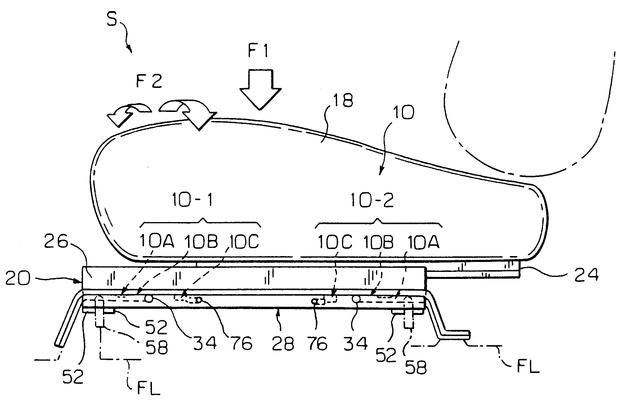
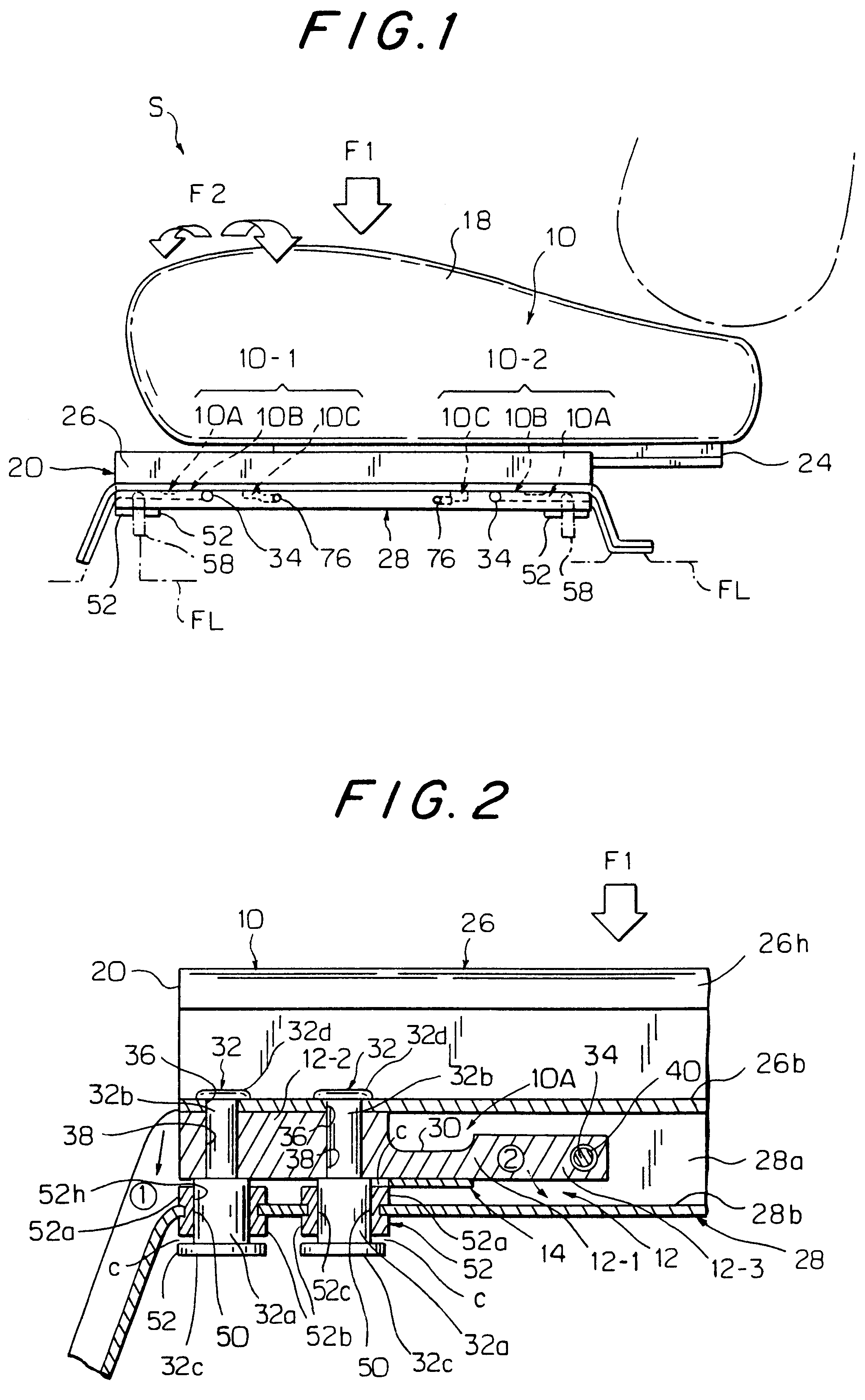
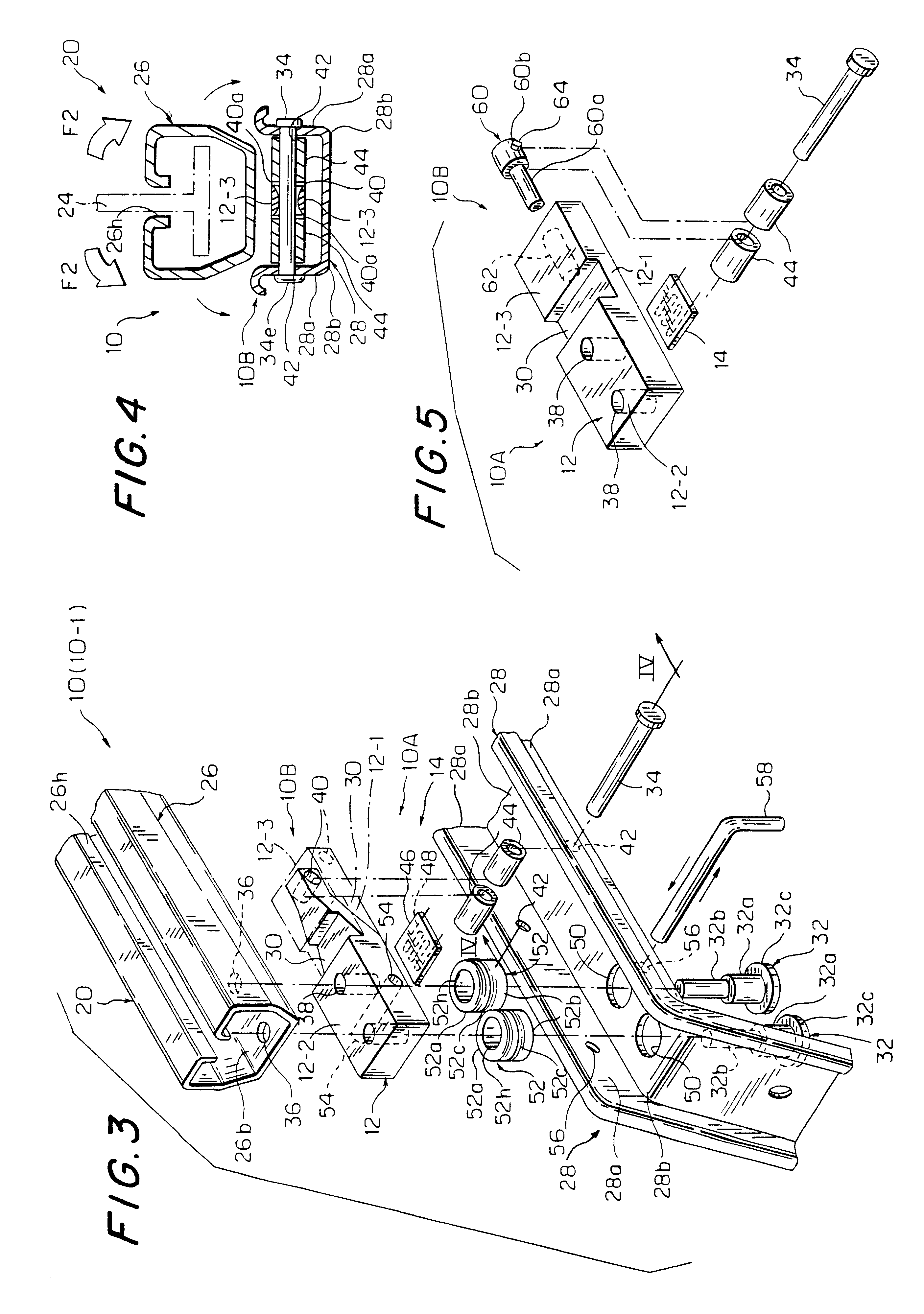
Referring to FIGS. 1 through 12, there is illustrated one preferred mode of load detection structure applicable to a vehicle seat in accordance with the present invention. Reference is first made to FIG. 1 in which designations (10) each generally represents a load detection structure provided between a slide rail device (20) and a support leg member (28) in a novel simplified manner with various structural features, which is a main novel aspect of the present invention as will be described. Also, as will be elaborated later, as far as the illustrated embodiment is concerned, the load detection structure (10) may preferably be embodied by a load detection means (10A) for detecting an amount of vertically applied downward load (F1) (i.e. a weight of an occupant on a seat (S)); a twist prevention means (10B) for preventing the load detection means (10A) from being twisted by laterally applied load (F2) (i.e. a leftward or rightward applied load or force); and an auxiliary linkage mean...


PUM

PropertyMeasurementUnit
diameteraaaaaaaaaa
elasticaaaaaaaaaa
displacementaaaaaaaaaa

Abstract

A load detection structure in a vehicle seat with a support leg member, which includes a block member of rigid yet resilient recovery property and a strain gauge attached thereon. The block member is interposed between the seat and support leg member, such that a securing portion thereof is secured to the seat, whereas a pivotal end portion thereof is rotatably pivoted to the support leg member. The securing portion is displaced in a vertical direction due to a vertical load applied to the seat, while the pivotal end portion is rotated, so as to cause deflection in the block member, which is detected by the strain gauge. It may be so arranged that the block member is rotatable about its central axis, thereby being prevented against twist due to a lateral load applied to the seat. An auxiliary linkage is provided to insure preventing such twist of block member.

Description

BACKGROUND OF INVENTION1. Field of the InventionThe present invention relates to a structure allowing for detection of a load applied to a vehicle seat. In particular, the invention is directed to such load detection structure for use in a vehicle seat.2. Description of Prior ArtRecent years have witnessed a tendency for various automatically controlled functions and mechanisms to be increasingly incorporated in vehicle or automobiles, including safety devices such as air bags for protecting passengers against a great impact automatically in response to a collision, as well as various kinds of seat position adjustment devices for automatically adjusting the positions of seat sensitive to driver's or passenger's physiques and seating conditions. With such automated control innovations, there have been also found technical improvements to a passenger detection system for detecting the presence and absence of a passenger or driver in a seat of vehicle in advance before actuating or sto...

Claims


Application Information

Patent Timeline
Patent Type & Authority Patents(United States)
IPC IPC(8): B60N2/00G01N3/08G01N3/14G01N3/06G01N3/00G01G3/14A47C7/62B60N2/90G01G19/12G01G19/52
CPCB60N2/002G01N3/14G01N2203/0676G01N2203/0033G01N2203/0019
Inventor KIMURA, TOSHIMITSU
Owner TACHI S CO LTD
Why Eureka
Try Eureka