Arrangement and method for dynamic control of the movements and course of a high-speed ship hull

a high-speed ship and dynamic control technology, applied in the direction of vessel movement reduction by foils, floating buildings, steering components, etc., can solve the problems of affecting the stability of the course,

Inactive Publication Date: 2003-02-18
LA ME
View PDF7 Cites 87 Cited by
  • Summary
  • Abstract
  • Description
  • Claims
  • Application Information

AI Technical Summary

Problems solved by technology

It is previously known that high-speed vessels of the type in question can be associated with certain problems, such as pitching and rolling tendencies and also difficulties in maintaining the correct floating position while in motion.
A contributory cause of such problems, for example with regard to passenger ferries, is that the load distribution between different journeys and / or trips can vary greatly depending on the number of cars and passengers and their positioning on board.
A specific problem associated with modern high-speed vessels of the type which is usually operated by water-jet drive is that they tend to not have very good course stability.
In the case of heavy seas from the stem, there is a certain risk that the manoeuvrability will be lost momentarily and the bow of the vessel will veer out to one side from the intended course (broach).
However, such previously known arrangements result in increased water resistance which leads to either a reduction in speed with maintained shaft power or increased fuel consumption at maintained speed because the shaft power must be increased in order to compensate for the increased resistance.
Furthermore, such previously known arrangements for increasing course stability in general make manoeuvring of the vessel in the lateral direction more difficult.
It is therefore not desirable to improve the course stability unilaterally at the expense of the manoeuvrability of this type of high-speed vessel.

Method used


Image

  • Arrangement and method for dynamic control of the movements and course of a high-speed ship hull
  • Arrangement and method for dynamic control of the movements and course of a high-speed ship hull
  • Arrangement and method for dynamic control of the movements and course of a high-speed ship hull

Examples


second embodiment

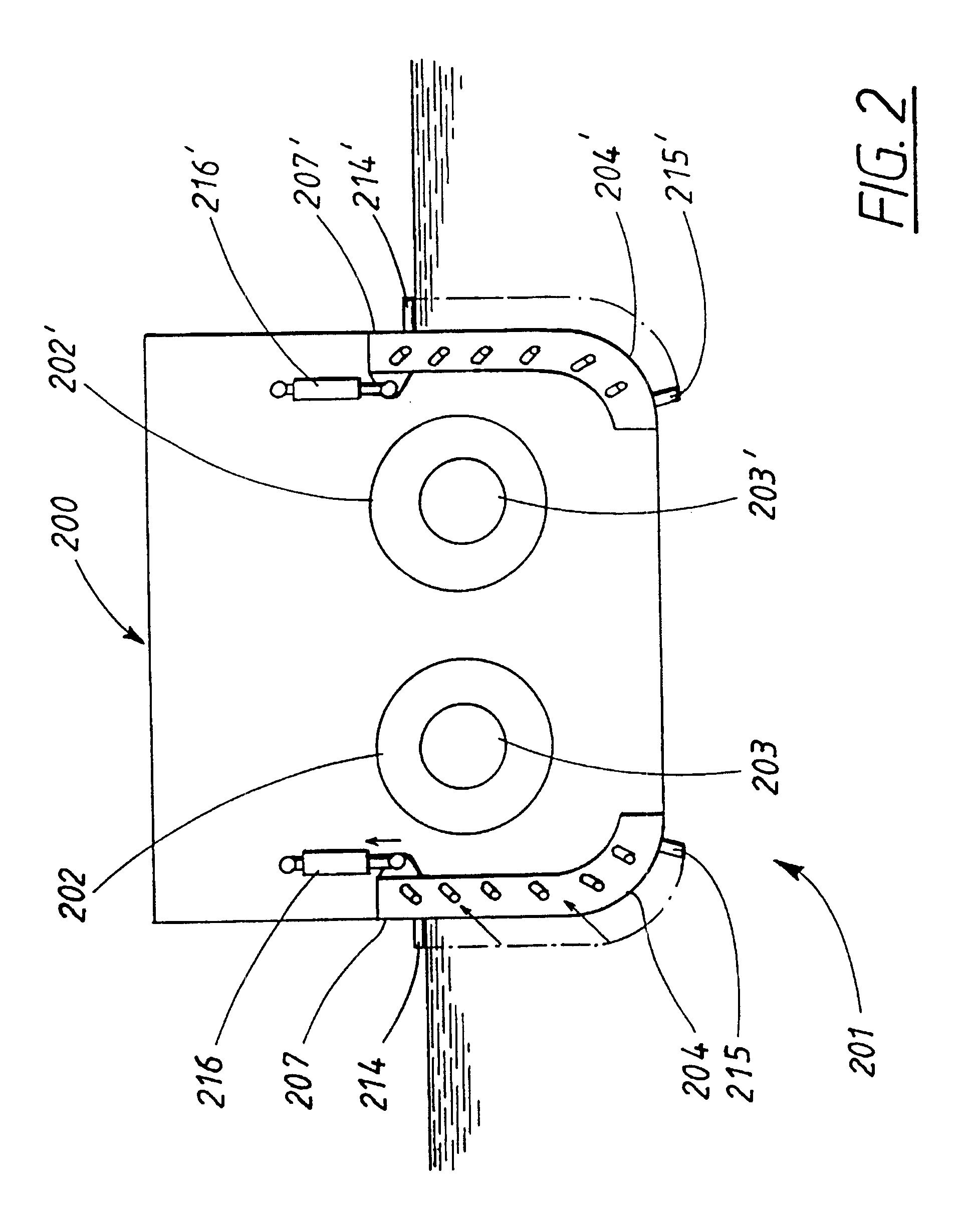
FIG. 2 shows a diagrammatic view from the rear of a high-speed vessel hull equipped with an arrangement according to the invention,

third embodiment

FIG. 3A shows a diagrammatic plan view from the rear of another high-speed vessel which is equipped with an arrangement according to the invention,

FIG. 3B shows diagrammatically one rear corner of the vessel shown in FIG. 3A, seen from above along the section A--A in FIG. 3A, and

FIG. 4 shows a simplified basic diagram of an arrangement according to the invention for the purpose of illustrating an embodiment of a method according to the invention.

PREFERRED EMBODIMENTS

first embodiment

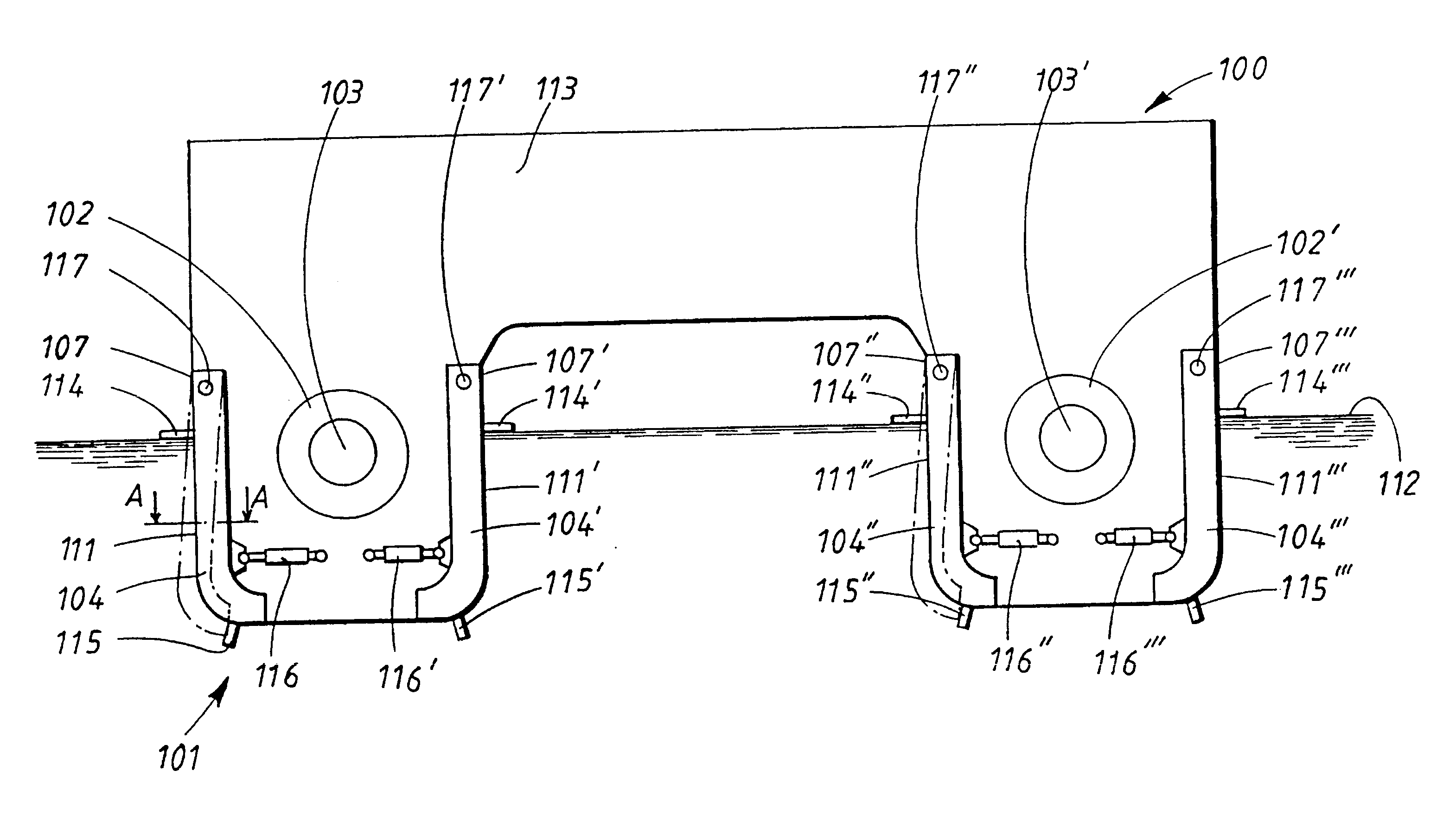
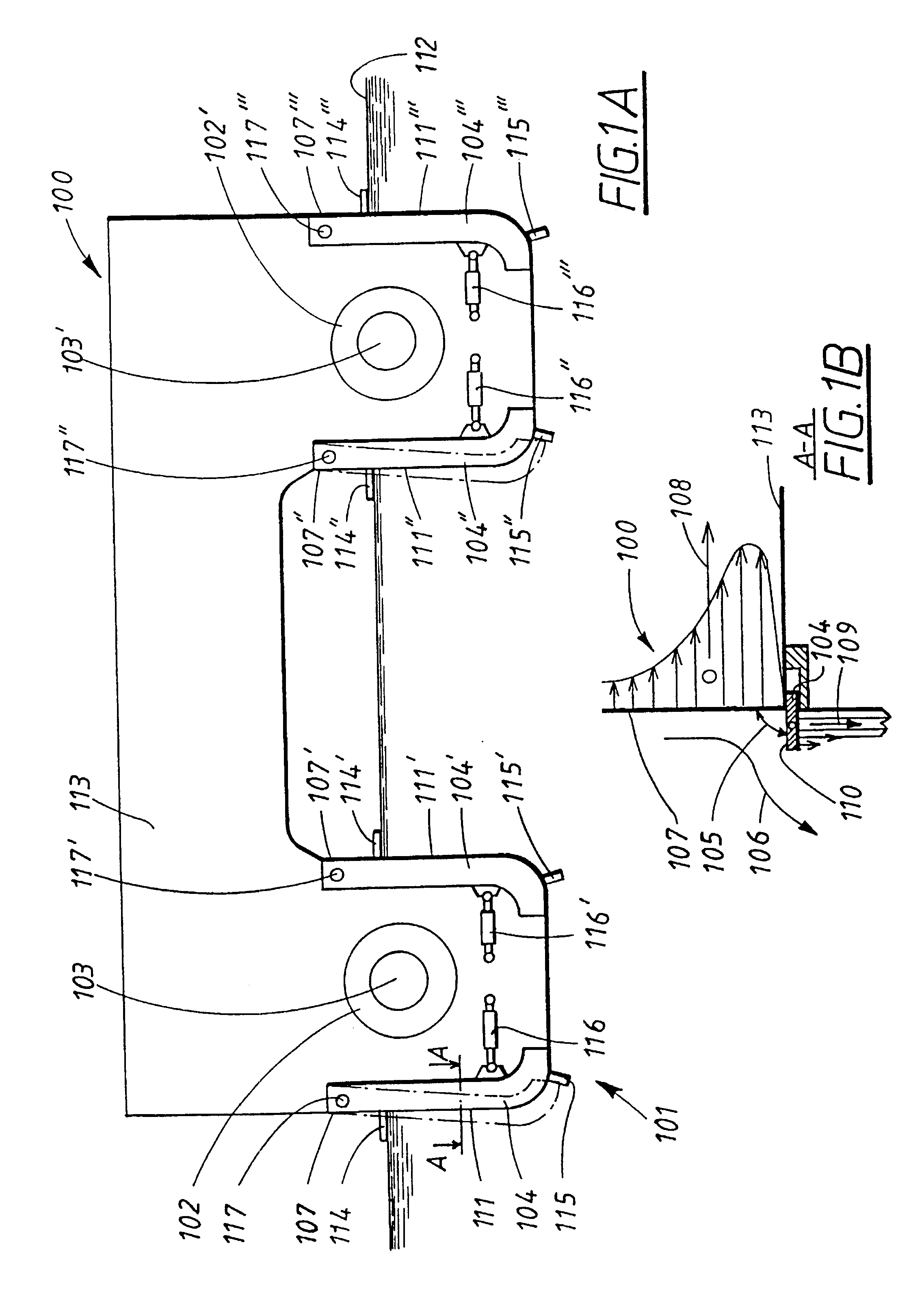
FIGS. 1A and 1B show diagrammatically a high-speed vessel with a hull 100 of the catamaran type, an arrangement 101 according to a first preferred embodiment of the invention having been arranged in association with the stern of the vessel. In the first embodiment, the vessel is provided with two propulsion members 102, 102' with course-changing means 103, 103' which consist of two water-jet units with rotatable nozzles and scoop-shaped members for directing the water jets. It is possible, however, to envisage embodiments of the arrangement according to the invention in which no course-changing means 103, 103' are present.

In the first embodiment, the arrangement 101 comprises four flap members 104, 104', 104", 104'" which are all arranged so as to be capable of being brought adjustably at an angle 105 in relation to a water flow 106 relative to an aft side surface 107 of the vessel hull 100.

In the first embodiment, a flap member 104, 104', 104", 104'" is arranged at four different t...


PUM


Abstract

The invention relates to an arrangement and a method for dynamic control of the movements and course of a high-speed vessel hull (100). The arrangement (101) comprises propulsion members (102, 102') and at least one flap member (104, 104', 104'', 104'''). In this connection, the flap member is arranged so as to be capable of being brought adjustably at an angle (105) in relation to a water flow (106) relative to an aft side surface (107) of the vessel hull (100) in order in this connection to generate force components (108, 109) which act on said vessel hull (100) and on a front side (110) of the flap member (104), the flap member (104) being arranged so that the force components (108, 109) generated are directed on the one hand towards the aft side surface (107) of the vessel hull and on the other hand towards the front side (110) of the flap member (104) in the water flow (106) relative to the aft side surface (107) so as in this way to be capable of bringing about a change in the movements and/or course of the vessel hull (100). The invention is particular intended for manoeuvring vessel hulls of high-speed vessels of the type which are provided with water-jet drive, that is to say vessels with a water-free stem while in motion, but can also be applied to other types of high-speed vessels.

Description

The present invention relates to an arrangement and a method for dynamic control of the movements and course of a high-speed vessel hull. The invention consists in that movable flap members are arranged at one or more transitions between the stern of the vessel and aft side portions of the vessel so as to be capable of being moved out in the lateral direction of the vessel hull and in this connection generate force components which act essentially in the lateral direction of the vessel hull. The invention also relates to a method for dynamic control of the movements and course of a high-speed vessel hull.The invention is intended in particular for manoeuvring vessel hulls of high-speed vessels of the type which are provided with water-jet drive, that is to say vessels with a water-free stem while in motion. Examples of such vessels are passenger ferries of single-hull or multi-hull type.The invention can, however, also be applied to other types of high-speed vessel than passenger fe...

Claims


Application Information

Patent Timeline
Patent Type & Authority Patents(United States)
IPC IPC(8): B63B39/00B63B39/06B63H25/44B63H25/00
CPCB63B39/061B63H25/44Y02T70/12B63B2001/325Y02T70/10
Inventor SVENSSON, BJORN
Owner LA ME
Why Eureka
Try Eureka