Matched crystal temperature compensation device

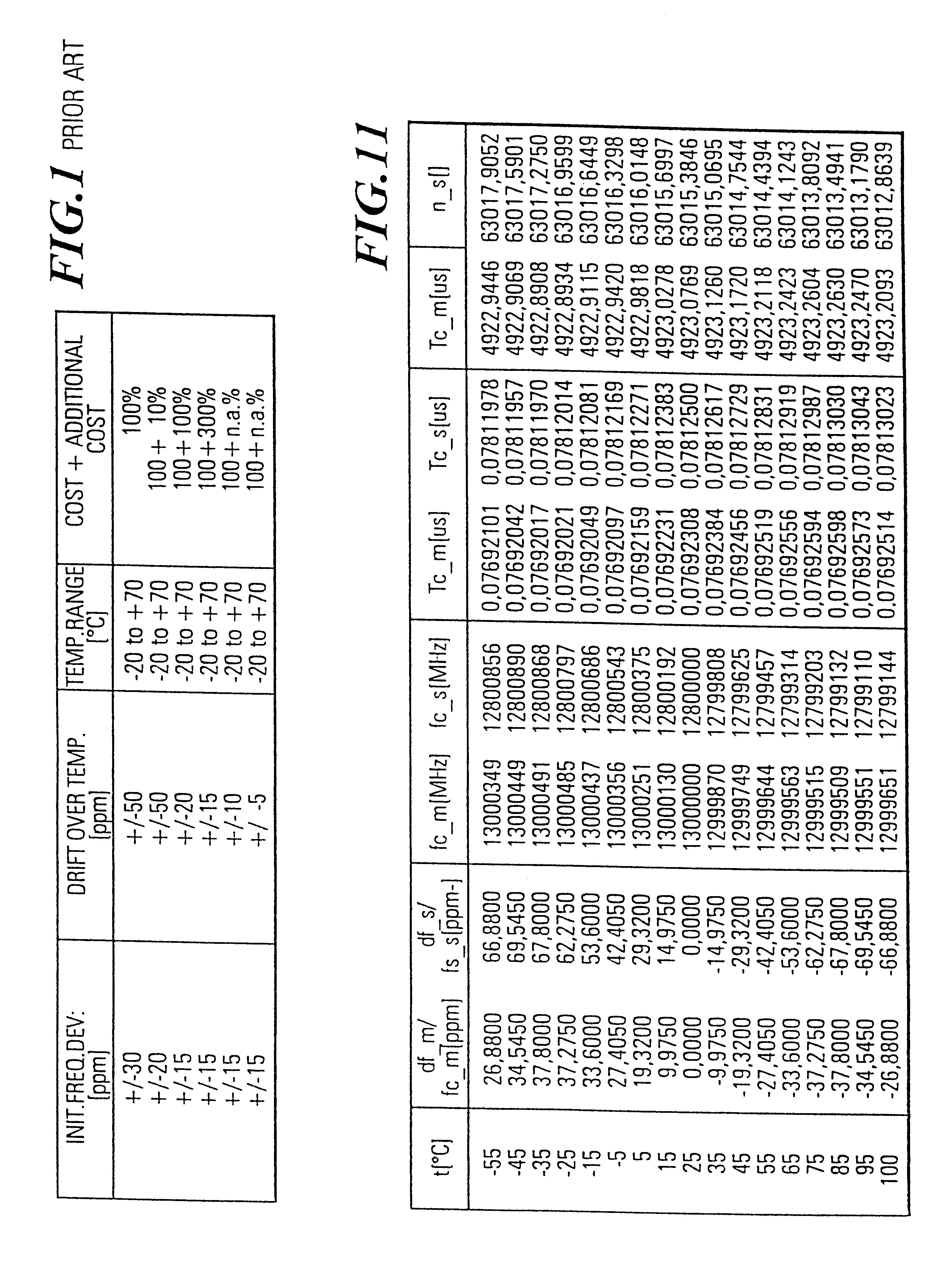
a temperature compensation and crystal technology, applied in the direction of heat measurement, optical radiation measurement, instruments, etc., can solve the problems of small initial frequency deviation and small frequency drift over temperature only being obtained at very high cost, and the approach is certainly a very high cost-intensive one, and it is difficult or at least cost-intensive to have such a precise knowledge of the temperature characteristic of the crystal when it is purchased from the manufacturer

Inactive Publication Date: 2003-02-18
OPTIS WIRELESS TECH LLC
View PDF6 Cites 41 Cited by
  • Summary
  • Abstract
  • Description
  • Claims
  • Application Information

AI Technical Summary

Problems solved by technology

As shown in FIG. 1, a small initial frequency deviation and a small frequency drift over temperature may only be obtained at very high cost.
Whilst the selection of a crystal with a low frequency drift over temperature may be a straight forward solution to build crystal oscillators with low frequency drift over temperature, this approach is certainly a very highly cost intensive one.
However, as will be explained below, it is difficult or at least cost intensive to have such a precise knowledge of the temperature characteristic of the crystal when it is purchased from the manufacturer.
However, the only thing that is not precisely known, but is needed for a precise temperature compensation is the cut-angle since it can not be measured on the crystal itself.
The tuning process is needed because the desired temperature characteristic of the crystals may not be preserved over large numbers of devices and furthermore NTC / PTC network is affected by tolerances.
Frequency measurements carried out at different temperatures are, however, time-consuming and require suitable equipment which makes temperature compensated crystal oscillators considerably more expensive than ordinary oscillators.
This can be very tedious and can require several steps in the production process and therefore adds undesirable costs to the product.
However, the exact determination of this temperature characteristic and a corresponding tuning network may increase the cost or may even be inaccurate since it is not possible to measure the frequency temperature characteristic with high accuracy.
However, the cut-angle of the selected crystal can not be measured as such.

Method used


Image

  • Matched crystal temperature compensation device
  • Matched crystal temperature compensation device
  • Matched crystal temperature compensation device

Examples


first embodiment

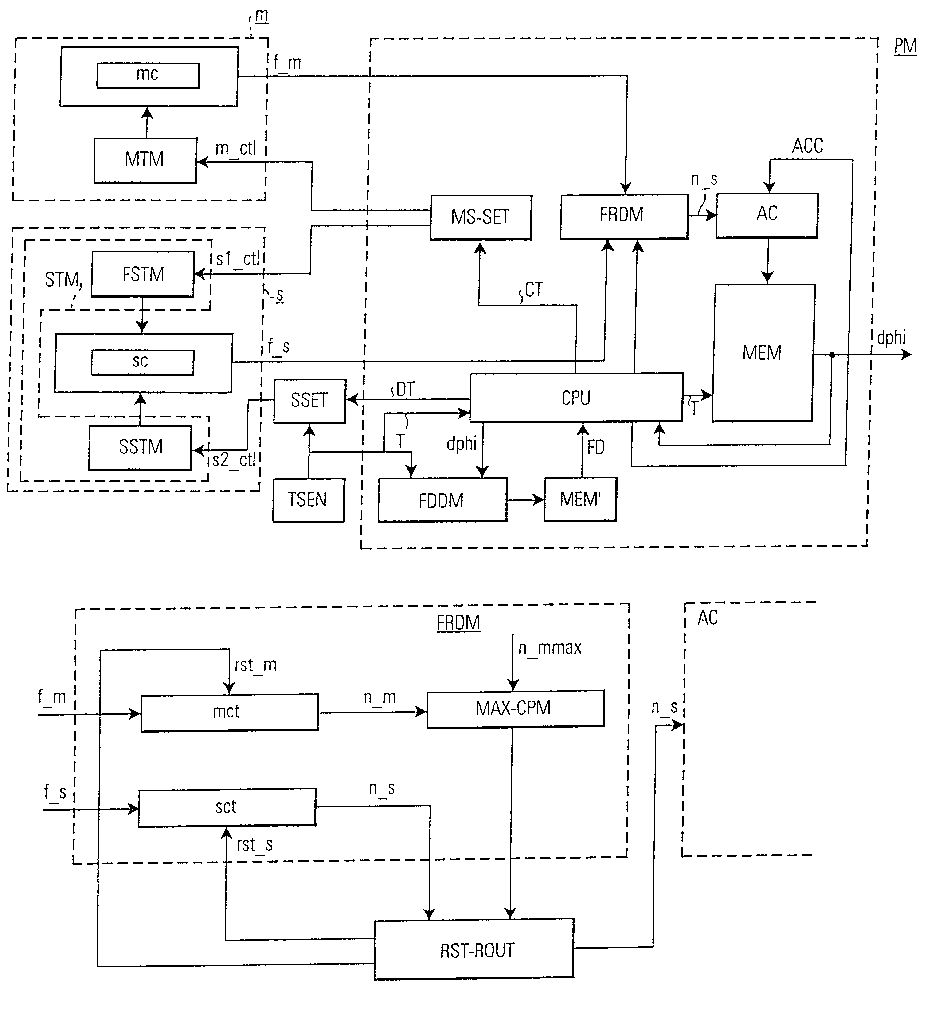
FIG. 7 shows a device for temperature compensation via a determination of the cut-angle of crystals used in oscillators according to the invention. This embodiment is based on the above described principle, i.e. to realize a temperature dependent counter state (frequency ratio) of the slave counter which is needed for the estimation of the temperature characteristic of the crystals, an additional temperature coefficient is added to the slave crystal oscillator and the frequency ratio parameter n_s is precalculated for various combinations of cut-angles and temperatures as shown in FIG. 12.

The operation principle of the device in FIG. 7 is similar to the operation principle in FIG. 5. However, in FIG. 7 the slave crystal oscillator temperature characteristic has been detuned with respect to the temperature characteristic of the master crystal oscillator and additional units and memories have been added for determining the cut-angle dphi.

FIG. 8 shows an embodiment of the frequency rat...

second embodiment

As explained above in the first embodiment, an additional linear temperature coefficient is added to the temperature characteristic of the slave crystal (oscillator) in order to detune the frequency characteristics of the slave crystal oscillator. It will be appreciated that this is essentially equivalent to a situation where two different crystals with different cut-angles are used in the slave and master oscillator. That is, if no detuning is applied to the temperature characteristic, the frequency ratio parameters can be used in order to evaluate how identical (or different) the cut-angles of two crystals used in the master and slave oscillators are. The second embodiment of the invention is described with reference to FIGS. 15, 16a, 16b relates to this aspect and this mode of operation will hereinafter be called the "calibration-mode" of operation.

When no active additional linear term or additional detuning is applied to the second oscillator the principle dependency of the freq...


PUM


Abstract

The invention relates to a device and a method for temperature compensation via the determination of cut-angles of a master and a slave crystal (mc, sc) employed in a master and slave oscillator (m, s). When the master and the slave oscillator (m, s) have been tuned to their center frequencies (fc_m, fc_s), then the temperature characteristic of the slave oscillator (s) is actively detuned with respect to the temperature characteristic of the master oscillator (m). In a detuned state a frequency ratio parameter (n_s) of the slave to the master output frequency (f_s / f_m) is determined and the cut-angle is determined by using this parameter (n_s) to read out the cut-angle dependent on the temperature (T) from a memory (MEM). The invention also relates to a temperature compensation device and method where two crystals of different cut-angles are used and a frequency ratio parameter is determined to determine the identity / symmetry or difference of the cut-angles. Particular useful applications of the invention are in dual-mode mobile telephones which require the use of at least two oscillators with different resonant frequencies.

Description

The invention relates to a device and a method for temperature compensation by a determination of the cut-angle of crystals used in oscillators. The invention relates also to device and a method for determining the identity (or difference) of the cut-angle of crystals used in oscillators.In particular, the invention addresses to problems how an effective temperature compensation can be achieved in a clock oscillator without the need of performing an estimation procedure which requires a temperature cycling during a production process. The temperature compensation technique of the present invention is particularly useful for all applications where two clock oscillators each having a crystal are used, e.g. in multistandard applications--one example being a GSM-AMPS dual mode operation). Since the temperature compensation using two "matched crystals" requires two crystals, it is most suitable for applications that need to have two reference frequencies for operation. For example, two r...

Claims


Application Information

Patent Timeline
Patent Type & Authority Patents(United States)
IPC IPC(8): H03L1/02H03L1/00H03B5/00H03B5/32H03B5/04
CPCH03B5/04H03L1/025H03B5/32H03L1/028
Inventor KODIM, WALTER
Owner OPTIS WIRELESS TECH LLC
Why Eureka
Try Eureka