Process for controlling the cooling air mass flow of a gas turbine set

a gas turbine and cooling air mass technology, which is applied in the direction of machines/engines, liquid degasification, separation processes, etc., can solve the problems of limiting the power and efficiency factor potential of the gas turbine s

Inactive Publication Date: 2003-02-25
ANSALDO ENERGIA IP UK LTD
View PDF19 Cites 55 Cited by
  • Summary
  • Abstract
  • Description
  • Claims
  • Application Information

AI Technical Summary

Problems solved by technology

With regard to the first proposed variant, it is to be stated in this connection that this leads, in operation without compressor cooling, to a cooling air mass flow which is far above what is required, markedly limiting the power and efficiency factor potentials of the gas turbine set.

Method used


Image

  • Process for controlling the cooling air mass flow of a gas turbine set
  • Process for controlling the cooling air mass flow of a gas turbine set
  • Process for controlling the cooling air mass flow of a gas turbine set

Examples


Embodiment Construction

The present invention has as its object to provide a process for regulating the cooling air supply of a gas turbine set, avoiding the disadvantages of the state of the art.

This is attained by the totality of the features of claim 1.

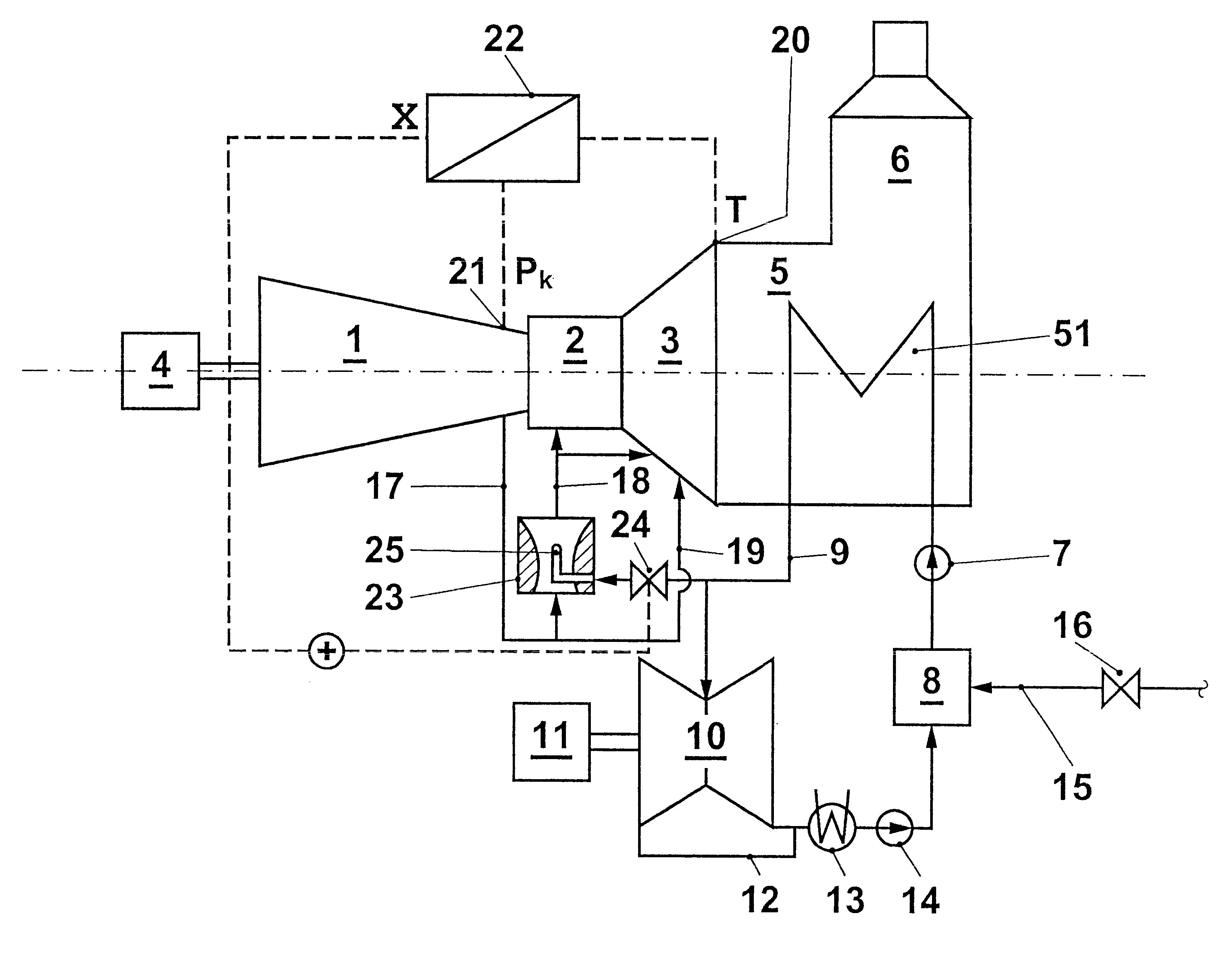
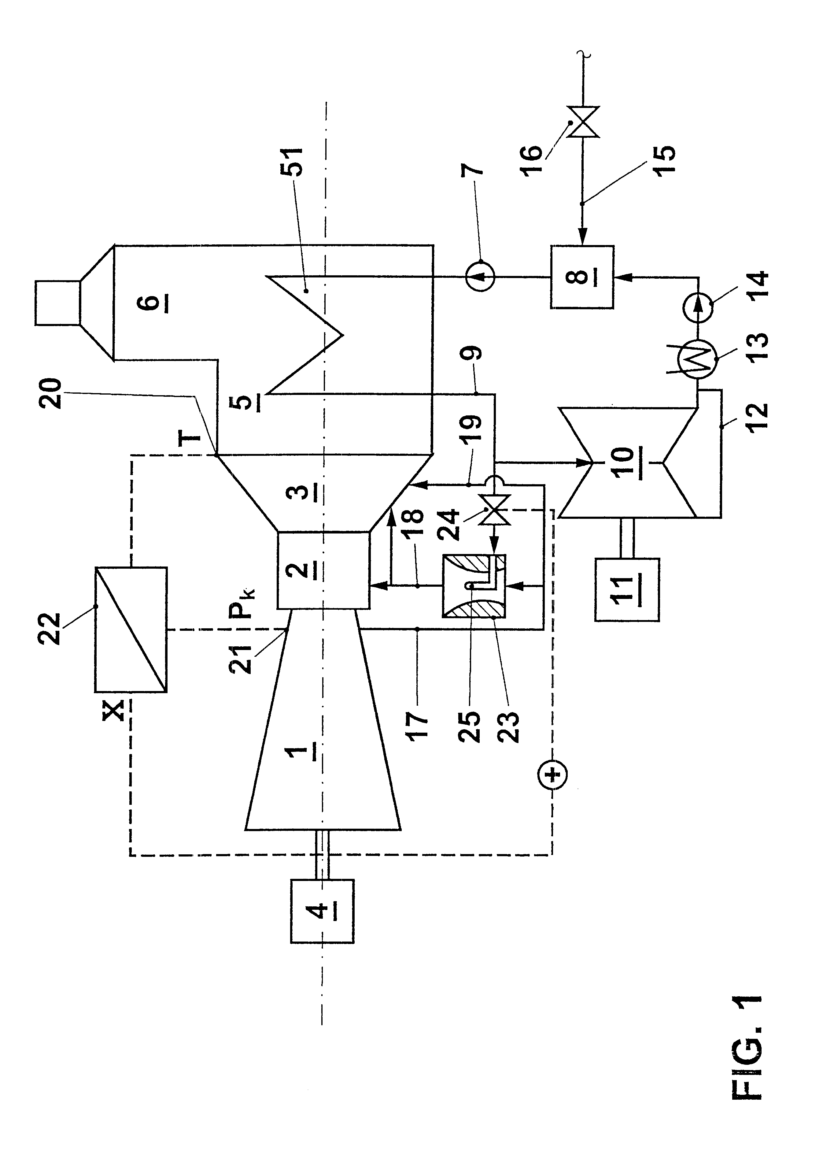
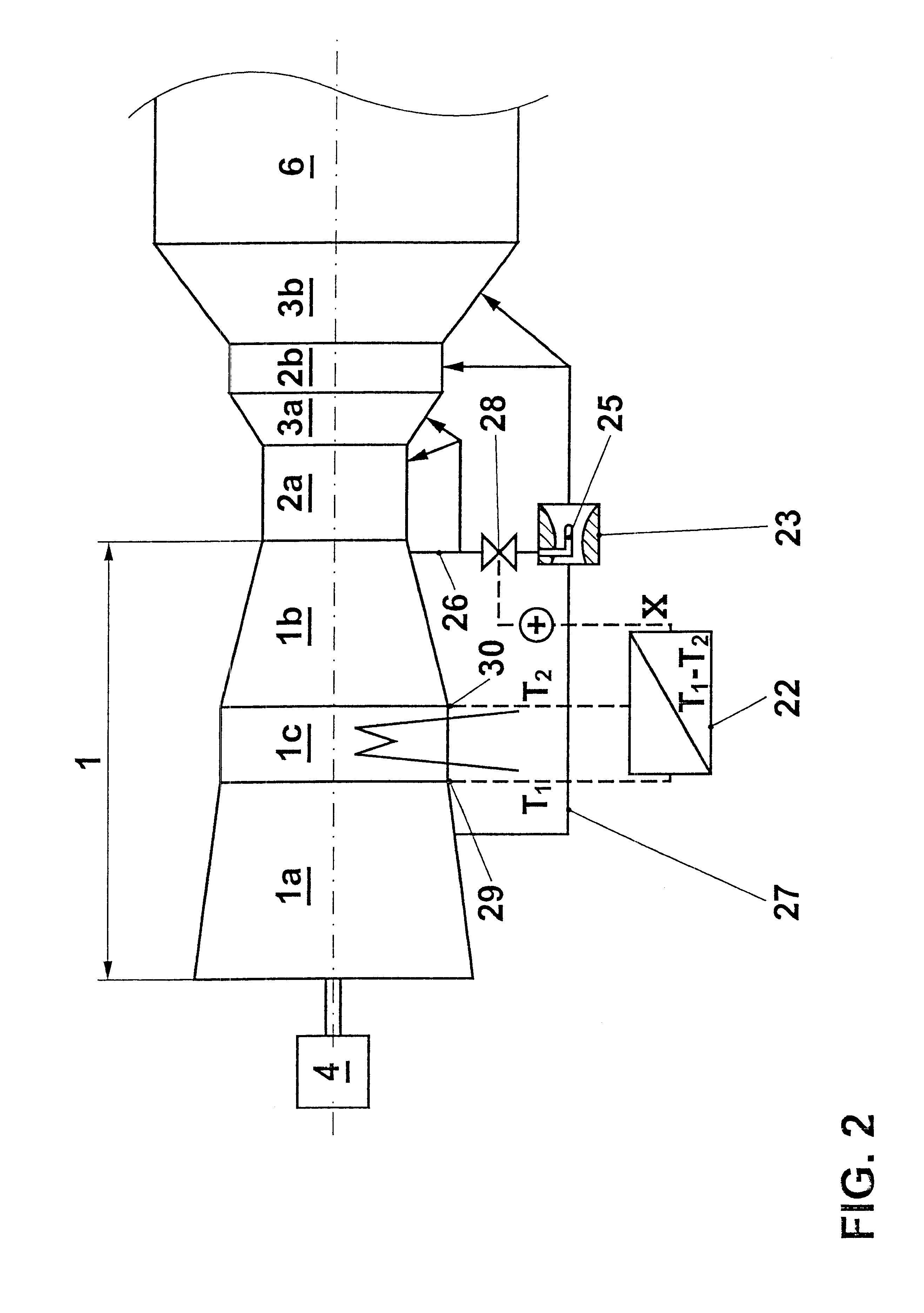
The core of the invention is thus, on the one hand to provide the cooling system of a gas turbine with suitable means which make possible a targeted external influence on the cooling air mass flow which flows there, and to control these means in dependence on a suitable operating parameter. This operating parameter contains, in one embodiment, which in particular finds application in variable compressor cooling, principally magnitudes which decisively affect or directly reproduce the pressure distribution and the mass flows in the cooling air system, or respectively around the cooling air system. The operating parameter can furthermore contain magnitudes which supply a measure for the hot gas temperature in the region of the components to be cooled, or fo...


PUM

PropertyMeasurementUnit
mass flowaaaaaaaaaa
pressureaaaaaaaaaa
cooling poweraaaaaaaaaa

Abstract

The invention gives a process for the control of the amount of cooling air of a gas turbine set (1, 2, 3). Suitable means (32, 33) are provided in the cooling system (26, 27) to enable the amount of cooling air to be varied. The control of this means takes place in dependence on an operating parameter (X). This is determined in a computer unit (22) by suitable combination of measured machine data (p1, p2).

Description

The invention relates to a process according to the preamble of claim 1.STATE OF THE ARTIntermediate cooling in the compressor of a gas turbine set is a well-known measure which can substantially contribute to an increase of the efficiency factor and the performance of a gas turbine set, particularly when the heat removed from the partially compressed working medium can be usefully employed at a place in the power station. EP 515 995 proposes in this regard to conduct the compressor air through a steam generator, and thus to produce an amount of steam which can be further used in the water-steam circuit of a combination plant. EP 781 909 and EP 898 645 propose supersaturating the air with water at the compressor inlet, so that a binary air-water-steam mixture enters the compressor. The successive evaporation of the water droplets introduced into the compressor leads to an intensive internal cooling of the compressor; the resulting steam is expanded in the turbine of the gas turbine ...

Claims


Application Information

Patent Timeline
Patent Type & Authority Patents(United States)
IPC IPC(8): F01K23/10F02C7/16F02C7/18
CPCF01K23/10F02C7/18F02C7/185F05D2260/212F05D2260/2322Y02T50/60
Inventor HOFFMANN, JUERGENROFKA, STEFANWAELCHLI, RENE
Owner ANSALDO ENERGIA IP UK LTD
Why Eureka
Try Eureka