Image display apparatus

a technology of image display and display screen, which is applied in the direction of selective content distribution, television systems, instruments, etc., can solve the problems of large fee for rent, inability to find optimal locations for appropriate architectural structures, and inability to meet the needs of site specificity,

Inactive Publication Date: 2003-02-25
SONY CORP
View PDF3 Cites 21 Cited by
  • Summary
  • Abstract
  • Description
  • Claims
  • Application Information

AI Technical Summary

Benefits of technology

Image data supplied from the image data supply means is converted into an optical beam which is then emitted, and the optical beam, when received, is demodulated to recover the image data which is then displayed on the image display means, so that even if the image data supply means and the image display means are installed at positions remote from each other, the image data can be optic-spatially transmitted. Therefore, a channel connection can be readily achieved without laborious and time-consuming works such as aerial-placing or underground installation of wired channels.

Problems solved by technology

For this purpose, however, the permission of the owner has to be obtained to utilize such architectural structures, and a large amount of fee will be charged for the rent.
In addition, appropriate architectural structures are not always found at locations optimal to the aerial-placing of the cables 101.
On the other hand, for burying the cables 101 underground, similar authorization must be obtained for the construction work, and the construction work may often be limited in terms of the time depending on sites.
In addition, the construction work will largely affect the civic life because of obstacle to the-traffic, tremendous noise caused thereby, and so on.
As appreciated, the placing of the cables 101, in either of aerial or buried forms, for constructing the large video display system 100 involves a large number of working steps, a great deal of labor, and a long time, thus implying a problem in the lack of smooth progress in installing the system.
Furthermore, since the large video display system 100 constitutes a single closed system, difficulties are encountered for connection of the system 100 with another system located at a different site.
Thus, a display associated with a large video device in another system would suffer from problems in that the same video sources must be provided in the other system, and very troublesome operations are required therefor.

Method used


Image

  • Image display apparatus
  • Image display apparatus
  • Image display apparatus

Examples


Embodiment Construction

Preferred embodiments of this invention will be described with reference to the accompanying drawings:

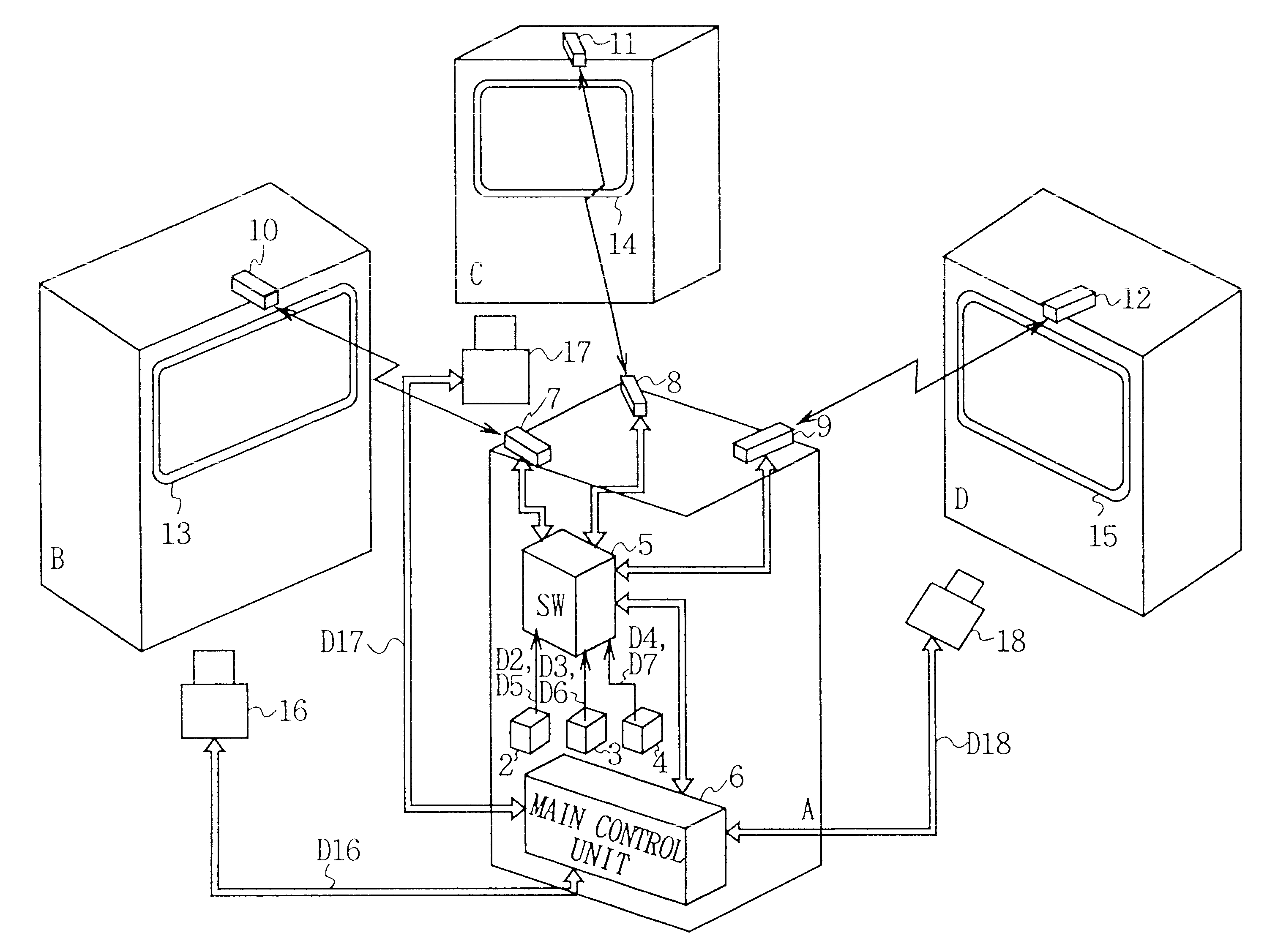
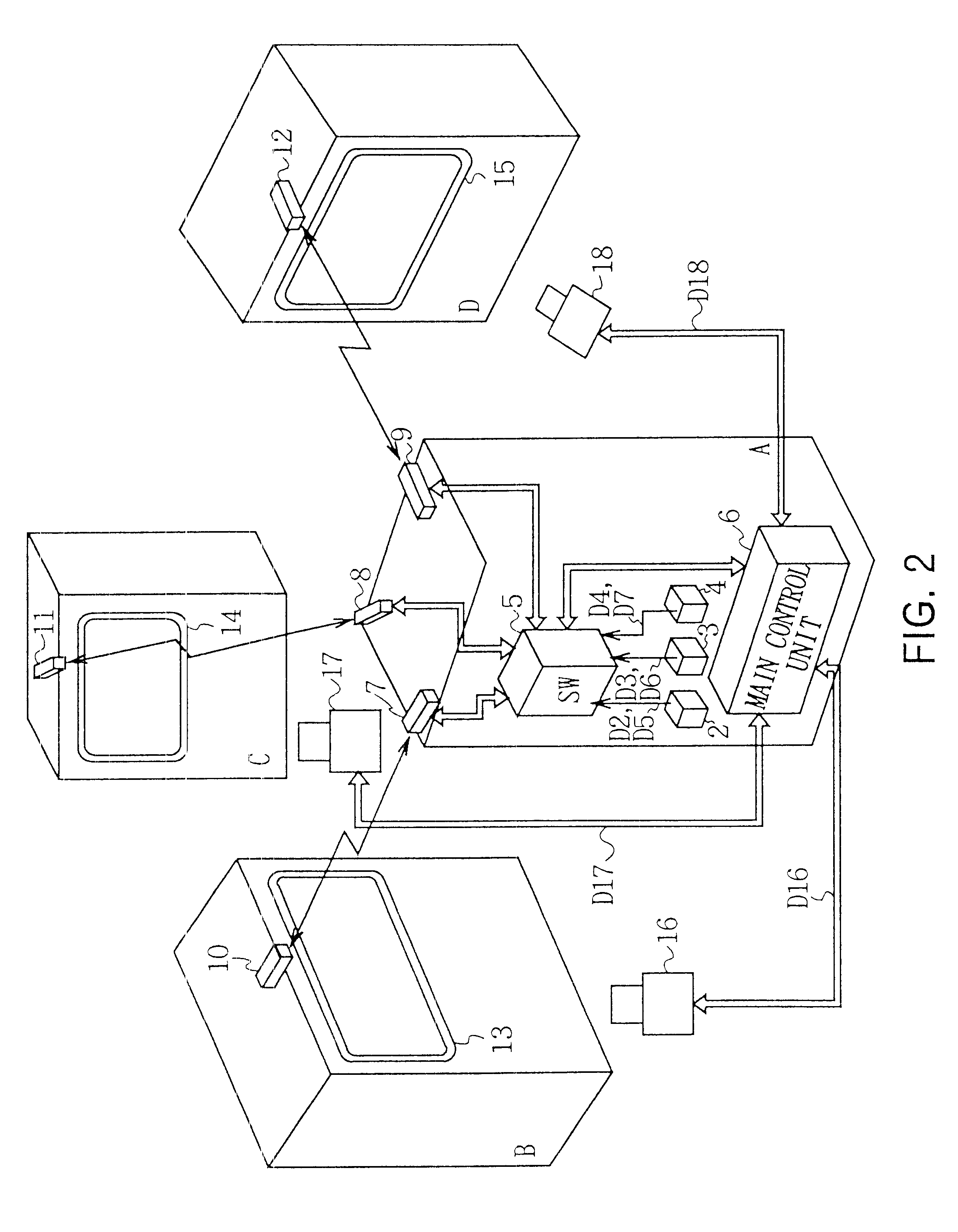
Referring to FIG. 2, numeral 1 generally shows a large video display system according to one embodiment of the present invention. Video data D2 to D4 and control data D5 to D7 corresponding to the video data D2 to D4 are respectively outputted to a switcher 5 from video supply units 2 to 4 each comprising a VTR installed in a building A. The switcher 5 selects the video data D2 to D4 and the control data D5 to D7 based on control of a main control unit 6 to send selected data to optical radio transmission devices 7 to 9.

For reference, the control data D5 to D7 may be a variety of information such as information indicating whether the video data D2 to D4 are still images or moving images, luminance information for controlling the brightness of the screen in accordance with the video data D2 to D4, and information indicative of the type of sound.

The switcher 5 can send the video data ...


PUM


Abstract

In an image display apparatus, an image data supply means is readily connected with an image display means through a channel, which are installed at positions remote from each other. The present invention provides an image data supply means for supplying image data, an optic-spatial transmission means on a transmission side for emitting optical beam which is modulated in accordance with the image data, optic-spatial transmission means on a reception side for receiving the optical beam emitted by the optic-spatial transmission means on the transmission side, and demodulating the optical beam to recover the image data, and an image display means for displaying an image based on the image data recovered by the optic-spatial transmission means on the reception side.

Description

1. Field of the InventionThis invention relates to an image display apparatus, and more particularly, is suitably applied to an image display apparatus for supplying desired video data to a large video device used on the roof of a building, in an event site, or the like.2. Description of the Related ArtA large video device having a large display is installed on the roof of a building, in an event site, or the like for displaying video images mainly for purposes of advertisement. A variety of commercial video images are simultaneously viewed by a large number of people with the large video device to achieve immense effects of advertisement.As illustrated in FIG. 1, for example, a large video display system 100 has a variety of components installed at sites remote from each other, where the components are connected by cables 101 such as communication cables made of twisted copper fine lines, coaxial cables and optical fiber cables. Video sources such as a video tape recorder (hereinaf...

Claims


Application Information

Patent Timeline
Patent Type & Authority Patents(United States)
IPC IPC(8): H04B10/10H04N7/10H04N7/16G09G5/00H04B10/00G06F3/00H04B10/079H04B10/11H04B10/116H04B10/54H04B10/564H04N21/414H04N21/61H04N21/81
CPCH04B10/1141H04B10/1149H04N7/106H04N21/812H04N21/41415H04N21/6106H04N7/165
Inventor MARUYAMA, TETSUOTSUCHIYA, MASAOGOTO, MASAHISAOTOBE, TAKAHI
Owner SONY CORP
Why Eureka
Try Eureka