Transcoder

Inactive Publication Date: 2003-02-25
TELEFON AB LM ERICSSON (PUBL)
View PDF7 Cites 188 Cited by
  • Summary
  • Abstract
  • Description
  • Claims
  • Application Information

AI Technical Summary

Problems solved by technology

Broadcast quality television requires an excess of 100 Mbit/s when transmitted in digital form which is expensive to transmit and requires links of high bandwidth.
The problem therefore is associated with the way in which video will be transmitted to subscribers with different requirements (picture quality, processing power, memory requirements, resolution, bandwidth, frame rate, etc.).
For coding methods involving motion compensation, new motion vectors have to be generated for the signal encoded according to the new coding scheme and this accounts for a large proportion of time for conventional transcoders.
Although t

Method used


Image

  • Transcoder
  • Transcoder
  • Transcoder

Examples


Embodiment Construction

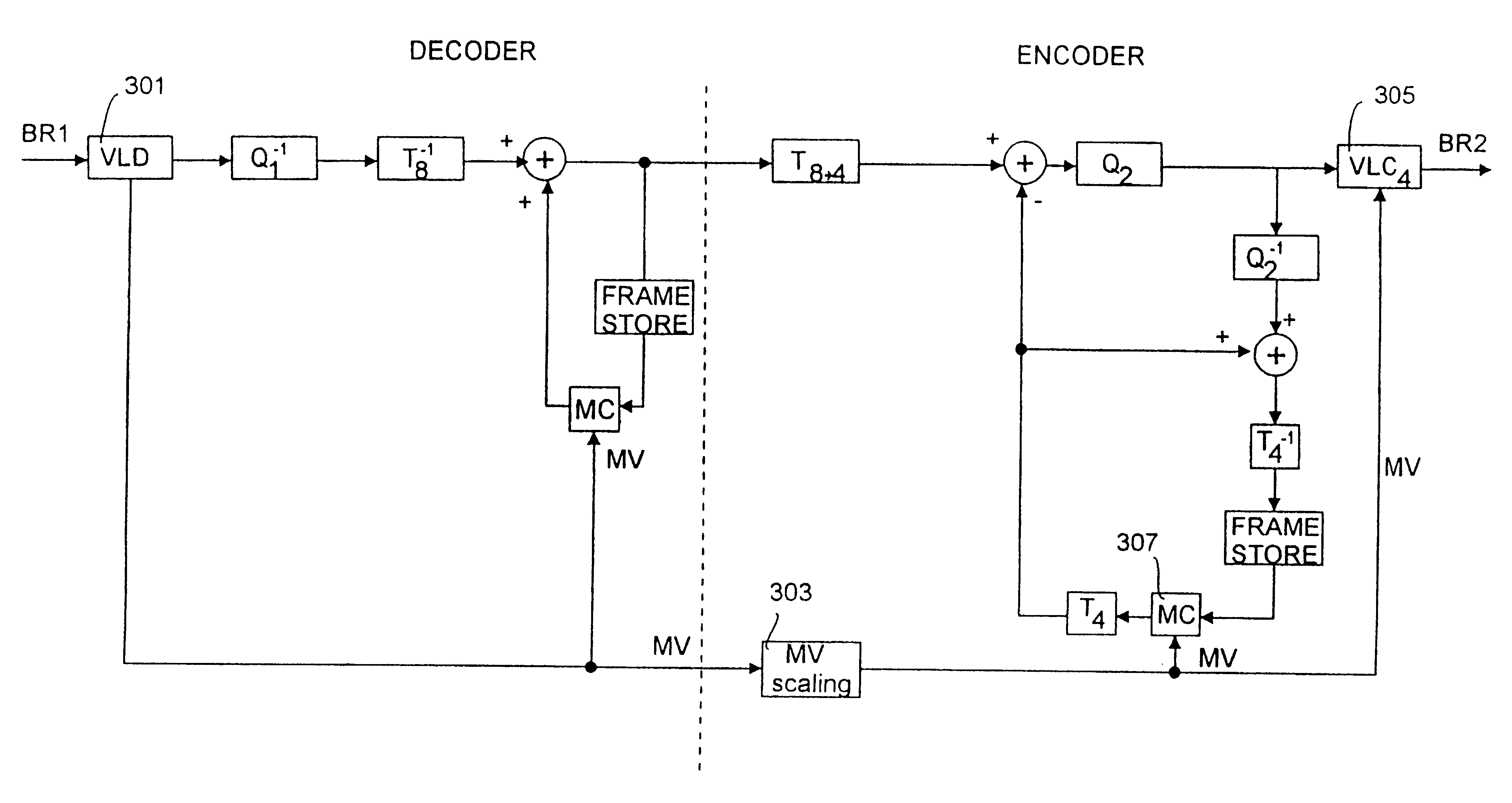
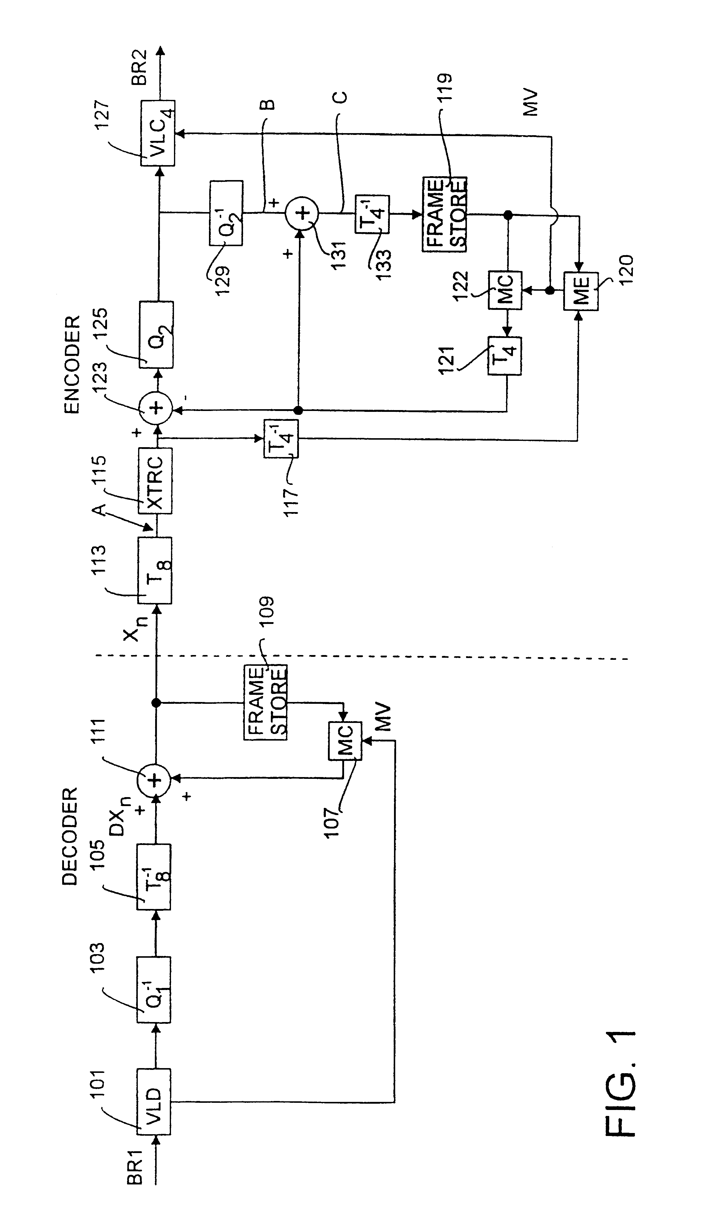
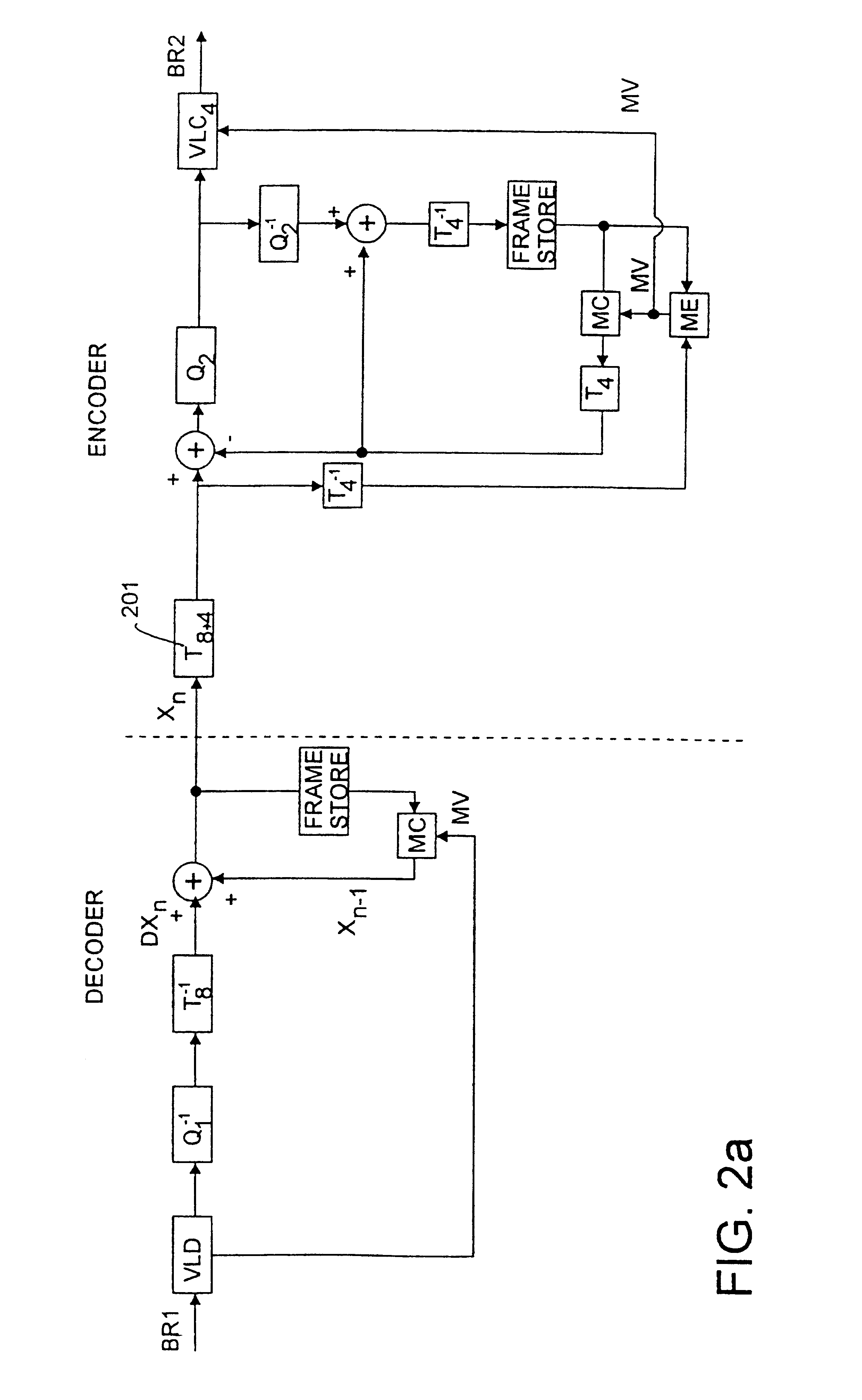
In FIG. 1 a diagram of a transcoder which can be used for both rate reduction and resolution reduction is shown. In the following examples a resolution reduction by a factor of 2 in each dimension is described, e.g. the transcoding of a CIF image to a QCIF image. However, the technique can be applied in similar manner for other resolution reduction factors and different formats. Thus, an incoming bit stream BR1 having a first bit rate, in this example a video signal encoded according to a first coding scheme employing motion compensation and DCT coding of the difference image, for example, at 128 kbit / s, CIF conforming to the H.263 standard is entering the transcoder. The bit stream BR1 is decoded in the Variable Length Decoder (VLD) block 101, where the received data is converted into quantised DCT coefficients, quantisation indices and motion vectors (MV). The DCT coefficients are passed through an inverse quantiser 103 and an inverse DCT processor 105 which converts the DCT coeff...


PUM


Abstract

In a transcoder means are provided for implementing a simultaneous change in rate and in resolution. In a preferred embodiment means are also provided for transferring incoming motion vectors or the like directly to the output encoder. The transcoder architecture is both suited for implementation in the spatial as well as in the frequency domain.

Description

The present invention relates to transcoders for conversion of signals between a first and a second coding scheme. The transcoders according to the invention are particularly suitable for converting two- and three-dimensional images and video signals.BACKGROUND OF THE INVENTION AND PRIOR ARTThere are many occasions when it is necessary to transmit moving picture television over long distances via a transmission link. Broadcast quality television requires an excess of 100 Mbit / s when transmitted in digital form which is expensive to transmit and requires links of high bandwidth. An acceptable degree of degradation in the picture quality can be introduced in order to reduce the information content being transmitted. Additionally or alternatively, compression coding techniques may be used which take advantage of the high degree of spatial and temporal redundancies in the video signals being encoded.There are also other applications where compression coding techniques are used. So, for ...

Claims


Application Information

Patent Timeline
IPC IPC(8): H04N7/26H04N7/32
CPCH04N19/48H04N19/90H04N19/40
Inventor CHRISTOPOULOS, CHARILAOSBJORK, NIKLAS
Owner TELEFON AB LM ERICSSON (PUBL)
Why Eureka
Try Eureka