Cross-channel interference

a cross-channel interference and interference technology, applied in the direction of transmission monitoring, electrical equipment, power management, etc., can solve the problems of time-consuming and easy to error, cross-channel interference is a significant source of noise in a given channel, and the test system is complex and expensive to implemen

Inactive Publication Date: 2003-02-25
ZARLINK SEMICON LTD
View PDF10 Cites 37 Cited by
  • Summary
  • Abstract
  • Description
  • Claims
  • Application Information

AI Technical Summary

Problems solved by technology

In many multi-channel electrical communication systems operating at radio or microwave frequencies, a significant source of noise in a given channel arises from cross-channel interference, i.e. due to the intermodulation of the signals carried by two or more other channels.
Such a t

Method used


Image

  • Cross-channel interference
  • Cross-channel interference
  • Cross-channel interference

Examples


Embodiment Construction

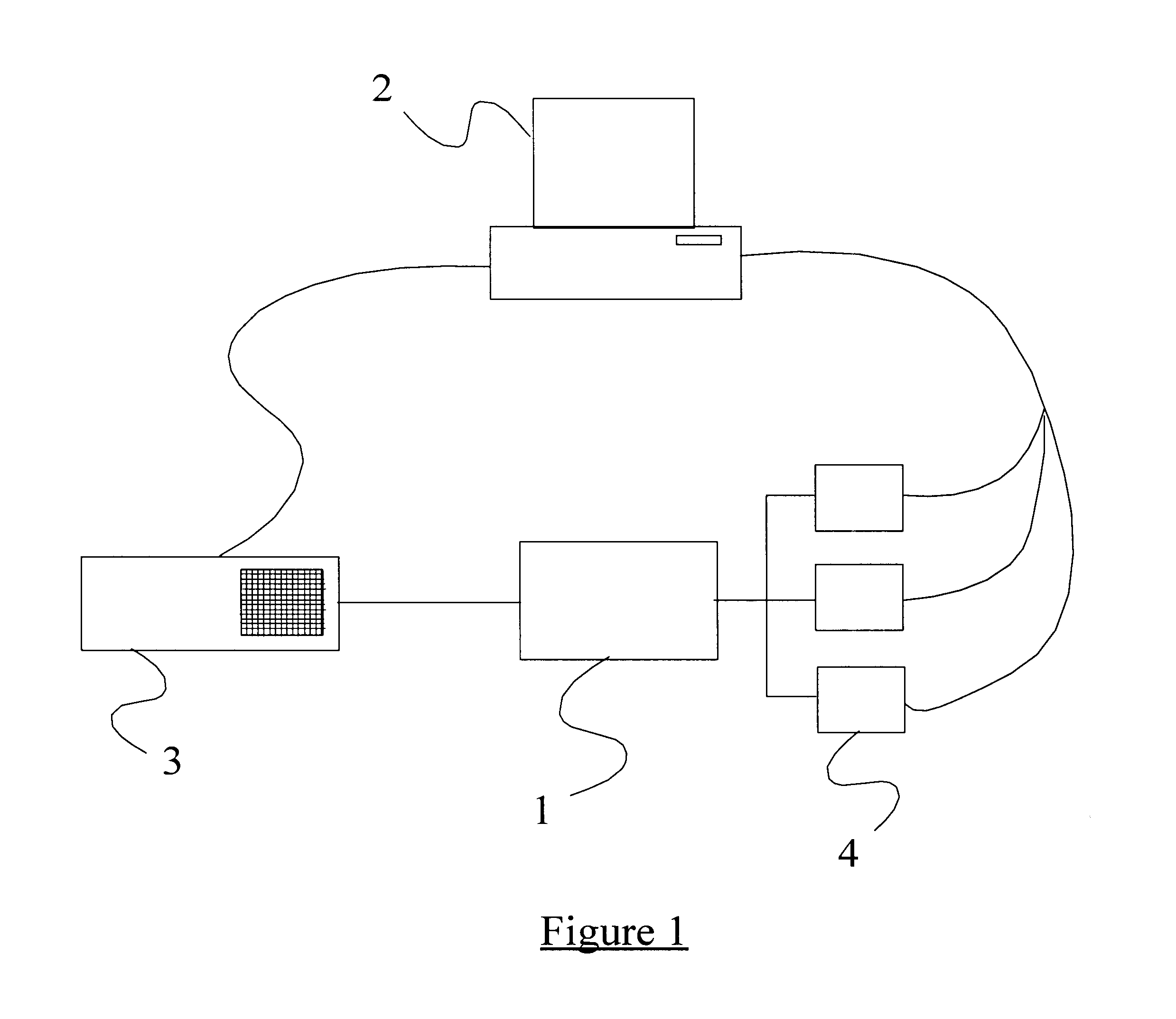
There is illustrated in FIG. 1 a system for testing a multi-channel communication receiver 1 to determine or predict cross-channel interference. The nature of the receiver 1 is not of interest here, although it may be, for example, a cable or satellite television receiver arranged to receive frequency division multiplexed (FDM) television signals. The test system is controlled by a computer 2 which may be a PC, workstation, or the like, and further comprises a spectrum analyser 3 and a set of signal generators 4. Both the spectrum analyser 3 and the signal generators 4 are controlled by the computer 2, with the output of the spectrum analyser 3 being delivered to the computer 2 for further processing.

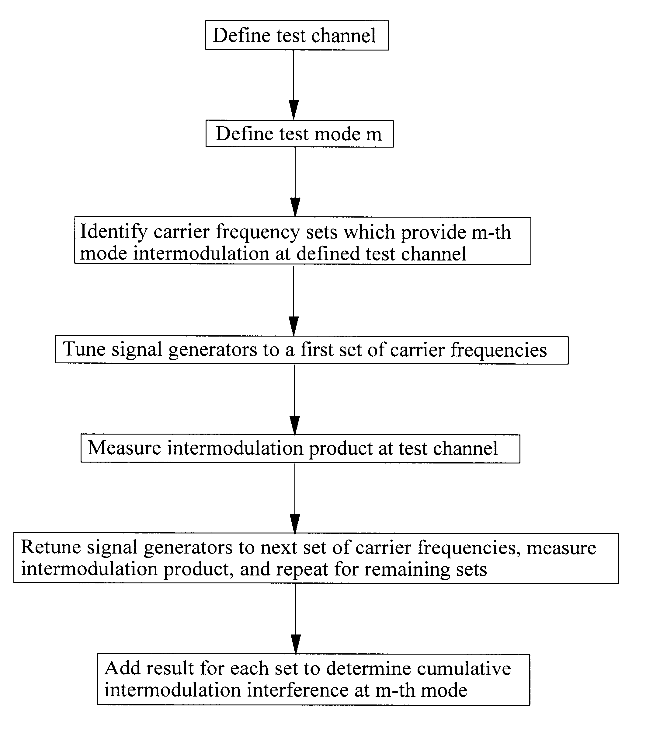
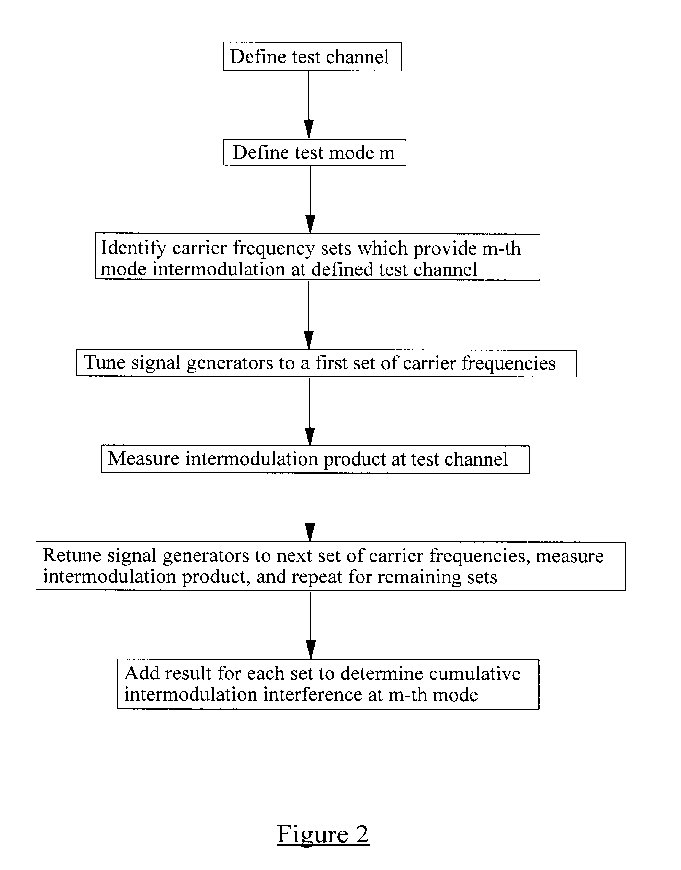
The various channels which the receiver 1 is intended to receive are centred upon respective carrier frequencies F. It is known that for second order intermodulation, the frequency relationships capable of interfering at a carrier frequency F.sub.c are those sets of carrier frequencies ...


PUM


Abstract

In a multi-channel electrical communication system 1, a method of estimating the interference level in a test channel due to the intermodulation of two or more other channels, where each channel is centred upon a carrier frequency. The method comprises, for a given m-th order mode, an initial step of identifying the set(s) of carrier frequencies, the m-th order linear combination of which gives rise substantially to the carrier frequency of said test channel. This process is carried out by a computer 2. For the or each of the identified set of carrier frequencies, signal generators 3 are tuned to respective ones of the carrier frequencies. The generated signals are applied to an input of the communication system 1, and the intermodulation interference at the carrier frequency of the test channel is measured at an output of the system 1.

Description

The present invention relates to cross-channel interference and in particular, though not necessarily, to the measurement of cross-channel interference levels in high frequency receivers.BACKGROUND TO THE INVENTIONIn many multi-channel electrical communication systems operating at radio or microwave frequencies, a significant source of noise in a given channel arises from cross-channel interference, i.e. due to the intermodulation of the signals carried by two or more other channels. In order to optimise system performance, designers seek to measure cross-channel interference levels as a step towards reducing interference.Considering for example a cable television receiver which is capable of receiving many individual television channels, the design stage of the receiver typically involves measuring the noise level in each channel due to cross-channel interference. This is carried out using an array of signal generators corresponding in number to the number of channels. Each signal ...

Claims


Application Information

Patent Timeline
IPC IPC(8): H04B17/00H04B7/005
CPCH04B17/0085H04B17/373H04B17/345H04W52/24H04W52/223
Inventor HICK, BRIAN HSAWYER, DAVID A
Owner ZARLINK SEMICON LTD
Why Eureka
Try Eureka