
Method and device for scanning the surface of an object with a laser beam

a laser beam and surface scanning technology, applied in the direction of optical elements, instruments, manufacturing tools, etc., can solve the problems of reducing the obtainable detail resolution and reducing the processing speed of the plotter system, and affecting the quality of the surface of the produced parts

Inactive Publication Date: 2003-03-18
FRAUNHOFER GESELLSCHAFT ZUR FOERDERUNG DER ANGEWANDTEN FORSCHUNG EV
View PDF6 Cites 34 Cited by
  • Summary
  • Abstract
  • Description
  • Claims
  • Application Information

AI Technical Summary

Benefits of technology

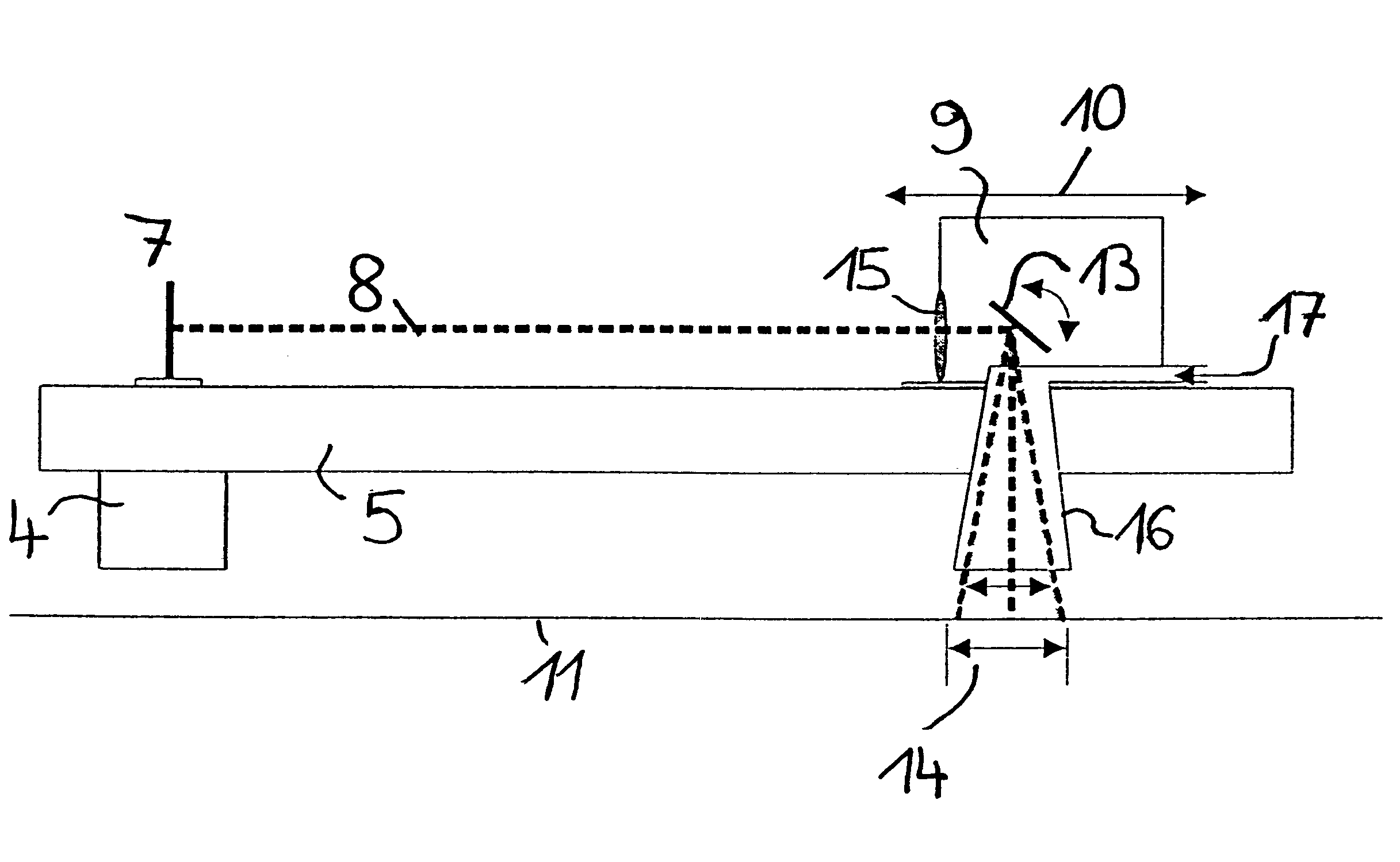
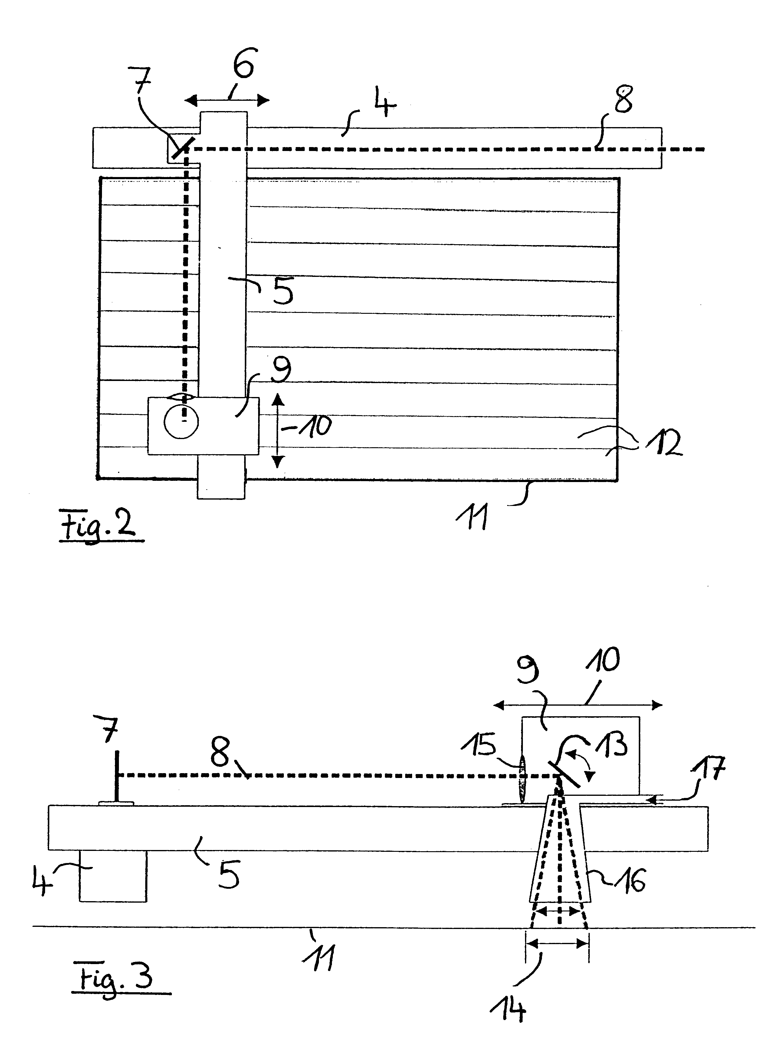
The invented device, therefore, combines the advantages of the rapid movement of a focused laser beam by means of a scanner with the advantages of the size of the processing field being independent of the focal length of the focusing optic as a result of using a plotter to move the beam. Furthermore, this device permits, in a simple manner, guiding a protective gas nozzle along with it. The laser beam is preferably focused with a short-focal-length optic to a diameter of <200 .mu.m and therefore simultaneously an area of any size can be worked with velocities of >200 mm / s.
By mounting a protective gas nozzle on the plotter, the protective gas nozzle is moved along with the plotter motion. However, as the nozzle is only moved along with the plotter but does not follow the laser movement by means of the scanner, the width of the nozzle aperture is selected larger or the same size as the width of the strip, thereby ensuring that there is a continuous flow of protective gas in the interaction zone of the laser beam.

Problems solved by technology

The disadvantage of scanner systems, however, is that if the preset turning angle of the mirror is maximum, the size of the workable area depends on the focal length of the focusing optic.
However, if all other optical elements are identical, increasing the focal length will also increase the focal diameter of the laser beam, thereby reducing the obtainable detail resolution and the quality of the surface of the produced parts.
However, the disadvantage of the plotter system is that, due to the mechanics involved, in comparison to a scanner system, only substantially lower processing velocities can be realized with a plotter system.
In particular, processing velocities of >200 mm / s preferred for selective laser melting cannot be realized with sufficient accuracy with a plotter system.

Method used


Image

  • Method and device for scanning the surface of an object with a laser beam
  • Method and device for scanning the surface of an object with a laser beam
  • Method and device for scanning the surface of an object with a laser beam

Examples


Embodiment Construction

The object of the present invention is solved with the device according to claim 1 and the process according to claim 10. Advantageous embodiments of this device and this process are the subject matter of the subclaims.

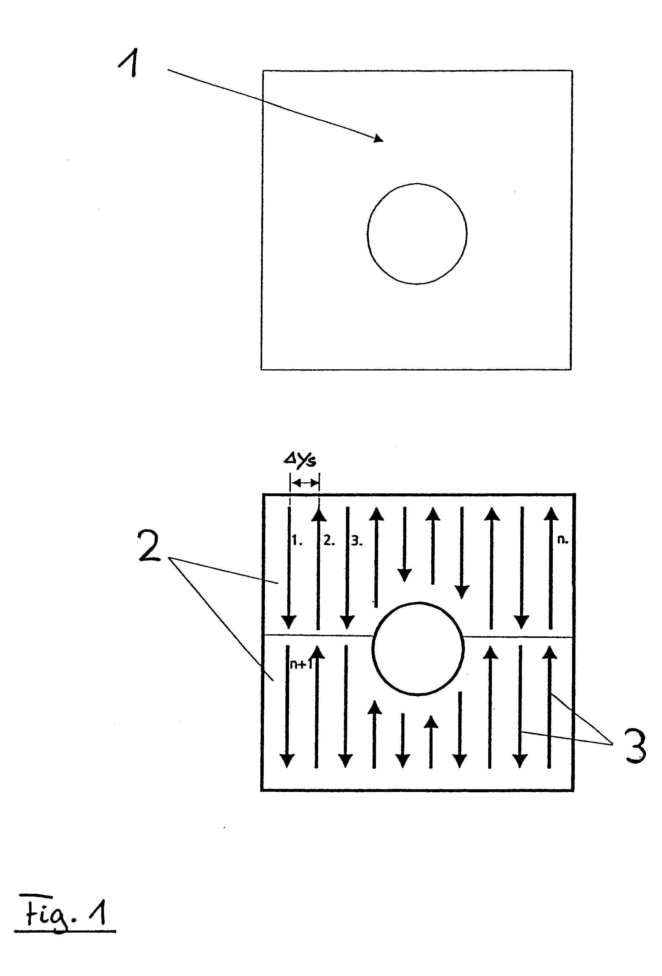
A key element of the present invention is that, in selective laser melting or laser sintering, when impinging on the processing area, the diameter of the laser beam is smaller than the width of the to-be-melted area respectively to-be-melted structure. Consequently, it is necessary to guide the laser on several adjacent paths to cover the entire to-be-melted area.

An element of the present invention is that it was understood that, by suited division of this area respectively of the laser paths on the area, two varyingly fast systems can be used to guide the laser beam. While the laser beam can be moved back and forth with high velocity to scan small subsections by means of a scanner optic, such as is known from the state of the art, the entire scanner optic is moved fu...


PUM

PropertyMeasurementUnit
Angleaaaaaaaaaa
Lengthaaaaaaaaaa
Angleaaaaaaaaaa

Abstract

The present invention relates to a device and a process using a laser beam to scan an area of an object, in particular, for selective laser melting of metal powder for fabrication of a mold. The device is provided with a plotter mechanic with two linear axes (4, 5) over which a carrier element can be positioned and moved, an optical means, which guides the laser beam to the carrier element or provides the laser beam at the carrier element, a scanning means (9) at the carrier element, which guides the laser beam to the area of the object and moves the laser beam back and forth in a presetable angle, a focusing optic (15) for focusing the laser beam (8) onto the area of the object (11). The plotter mechanic is disposed in such a manner that the plotter mechanic can position and move the carrier element at a distance over the area of the object (11), which distance permits the use of a focusing optic (15) of short focal length for focusing said laser beam to a diameter of <200 mum in the area of the object (11). This device combines the advantages of rapid movement of a focusing laser beam by using a scanner with the advantages of the size of the processing field being independent of the focal length of the focusing optic by using a plotter to move the beam.

Description

The present invention relates to a device and process using a laser beam to scan an area of an object, in particular for selective laser melting a metallic powder for fabricating a mold, for example, a prototype of a component.The present invention relates predominantly to a technology referred to as rapid prototyping. Rapid prototyping processes are employed in product development to shorten product development time and increase product quality, which is made possible by the fact that with rapid prototyping processes prototypes can be quickly produced directly from the 3D CAD model, thereby obviating the hitherto required time-consuming creation of a NC program for milling, eroding or fabrication of form-giving tools.The object of the development of new, respectively further development of present, rapid prototyping processes is to be able to process materials that are as close as possible to the series material or even identical to it. This especially applies to metallic prototype...

Claims


Application Information

Patent Timeline
IPC IPC(8): B23K26/10B22F3/105G02B26/10B23K26/04B23K26/08
CPCB23K26/10B22F3/1055Y02P10/25B22F10/28B22F12/49B22F12/44B22F12/70
Inventor MEINERS, WILHELMWISSENBACH, KONRADGASSER, ANDRES
Owner FRAUNHOFER GESELLSCHAFT ZUR FOERDERUNG DER ANGEWANDTEN FORSCHUNG EV
Learn More