Semi-coaxial horn antenna

a horn antenna and coaxial technology, applied in the field of horn antennas, can solve the problems of short frequency spectrum, and inability to meet the needs of uwb antennas with wide bandwidth, and achieve the effect of avoiding the occurrence of uwb antennas with large bandwidth, and avoiding the occurrence of uwb antenna

Inactive Publication Date: 2003-03-25
TDC ACQUISITION HLDG
View PDF18 Cites 139 Cited by
  • Summary
  • Abstract
  • Description
  • Claims
  • Application Information

AI Technical Summary

Problems solved by technology

In today's communications environment, frequency spectrum is in short supply and is very crowded.
In many situations, however, wider bandwidths may be required.
Conventional UWB antennas with wide bandwidths are physically large antennas, and thus impractical for most common uses.
In other words, the physical size of conventional UWB antennas can be a problem in applications that require a portable system that utilizes a conventional UWB antenna.

Method used


Image

  • Semi-coaxial horn antenna
  • Semi-coaxial horn antenna
  • Semi-coaxial horn antenna

Examples


Embodiment Construction

1. Impulse Radio Basics

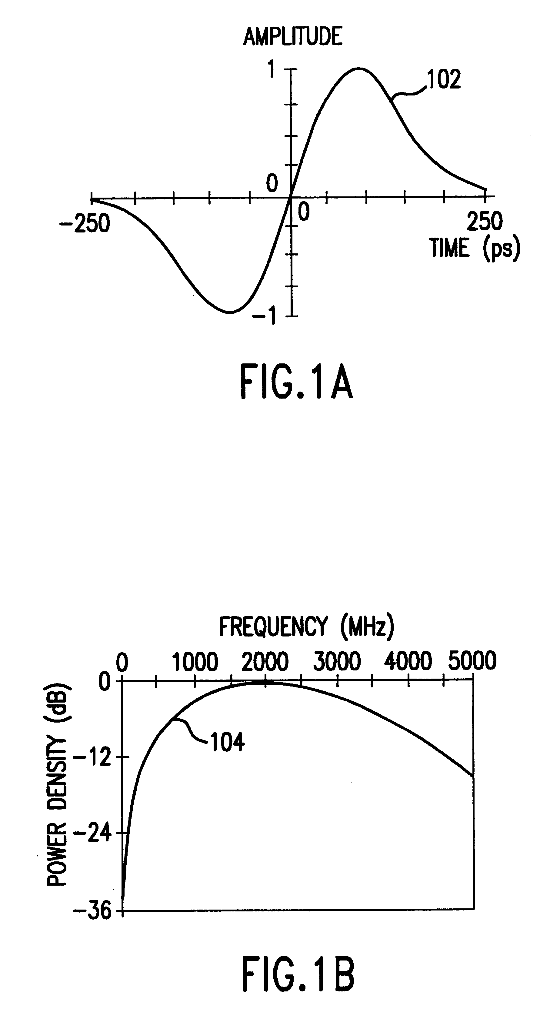
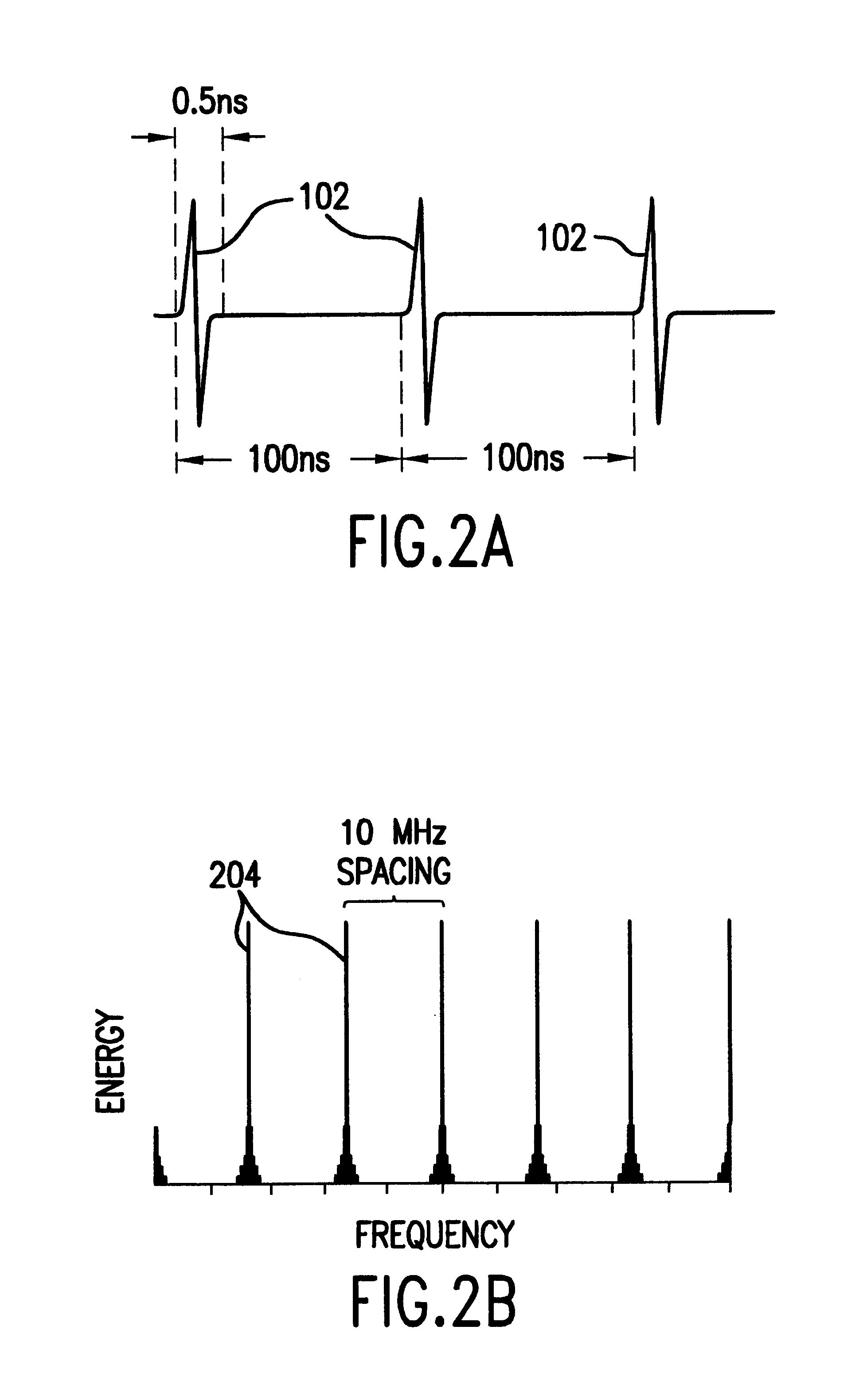
This section is directed to technology basics and provides the reader with an introduction to impulse radio concepts, as well as other relevant aspects of communications theory. This section includes subsections relating to waveforms, pulse trains, coding for energy smoothing and channelization, modulation, reception and demodulation, interference resistance, processing gain, capacity, multipath and propagation, distance measurement, and qualitative and quantitative characteristics of these concepts. It should be understood that this section is provided to assist the reader with understanding the present invention, and should not be used to limit the scope of the present invention.

Impulse radio communications was first fully described in a series of patents, including U.S. Pat. Nos. 4,641,317 (issued Feb. 3, 1987), 4,813,057 (issued Mar. 14, 1989), 4,979,186 (issued Dec. 18, 1990) and 5,363,108 (issued Nov. 8,1994) to Larry W. Fullerton. A second generation of...


PUM


Abstract

A semi-coaxial horn antenna transmits and receives electromagnetic waves, including impulse radio waves. The antenna includes an inner conductor that is surrounded by a cone-shaped dielectric, and an outer conductor that is conformally attached to the cone shaped dielectric. In embodiments, the inner conductor is a hollow metallic cylinder that is able to slide over a separate metal shaft, which may be part of a portable hand-tool device. The dielectric constant of the cone shaped dielectric may be selected to match a target medium. The outer conductor has a cross-section that is substantially an arc shape, and defines a sector angle phi that determines an impedance along the length of the antenna.

Description

1. Field of the InventionThe present invention generally relates to antennas, and more specifically to a semi-coaxial horn antenna.2. Related ArtThe radio transmission of both analog and digital information has normally been effected by one of two methods. In one, referred to as an amplitude modulation, the amplitude of a continuous sinusoidal carrier signal is modulated according to an information signal. When the amplitude modulated signal is received at a receiving location, the reverse process (that is, demodulation of the carrier) is preformed to recover the information signal. The other method employs what is termed frequency modulation. In frequency modulation, the frequency of the carrier signal is modulated in accordance with the information signal. During demodulation, circuitry is employed that performs frequency discrimination, which converts frequency variations in the carrier signal to an amplitude output that is in accordance with the original modulation. In both syst...

Claims


Application Information

Patent Timeline
Patent Type & Authority Patents(United States)
IPC IPC(8): H01Q13/08H01Q9/04H01Q9/00
CPCH01Q9/005H01Q13/08H01Q9/0471
Inventor SCHANTZ, HANS G.
Owner TDC ACQUISITION HLDG
Why Eureka
Try Eureka