
Thermal noise random pulse generator and random number generator

Inactive Publication Date: 2003-04-01
L E TECH
View PDF6 Cites 44 Cited by
  • Summary
  • Abstract
  • Description
  • Claims
  • Application Information

AI Technical Summary

Benefits of technology

FIG. 9C is a circuit diagram of a thermal noise element in the form of a Zener diode having a resistance value of R.sub.s and a noninverting amplifier connected thereto.
FIG. 9D is a circuit diagram of a thermal noise element in the form of a light-emitting diode (LED) having a resistance value of R.sub.s and a noninverting amplifier connected thereto
FIG. 9E is a circuit diagram of a thermal noise element in the form of a transistor having a resistance value of R.sub.s and a noninverting amplifier connected thereto.
FIG. 9F is a circuit diagram of a thermal noise element in the form of an inductor having a resistance

Problems solved by technology

While a physical random number generator that utilizes the decay products of a radioactive source provides the advantage that it can easily generate the true random numbers, it is accompanied by a number of disadvantages including that it involves a complex manufacturing process and high manufacturing cost because of the use of a radioactive source and that a device with radioactive source has difficulty to be socially accepted because of the regulation of radioactivity and environmental assessment in the use of radioactive substances.
It is impossible to enclose a known random number generators designed to supply an electric current to a resistor in order to utilize it as thermal noise source in a portable card or an integrated circuit (IC) because it requires the use of specifically designed devices including a piece of hardware for generating random numbers and a processing circuit for removing the 1 / f noise that are generated as a result of supplying an electric current to the noise source.

Method used


Image

  • Thermal noise random pulse generator and random number generator
  • Thermal noise random pulse generator and random number generator
  • Thermal noise random pulse generator and random number generator

Examples


Embodiment Construction

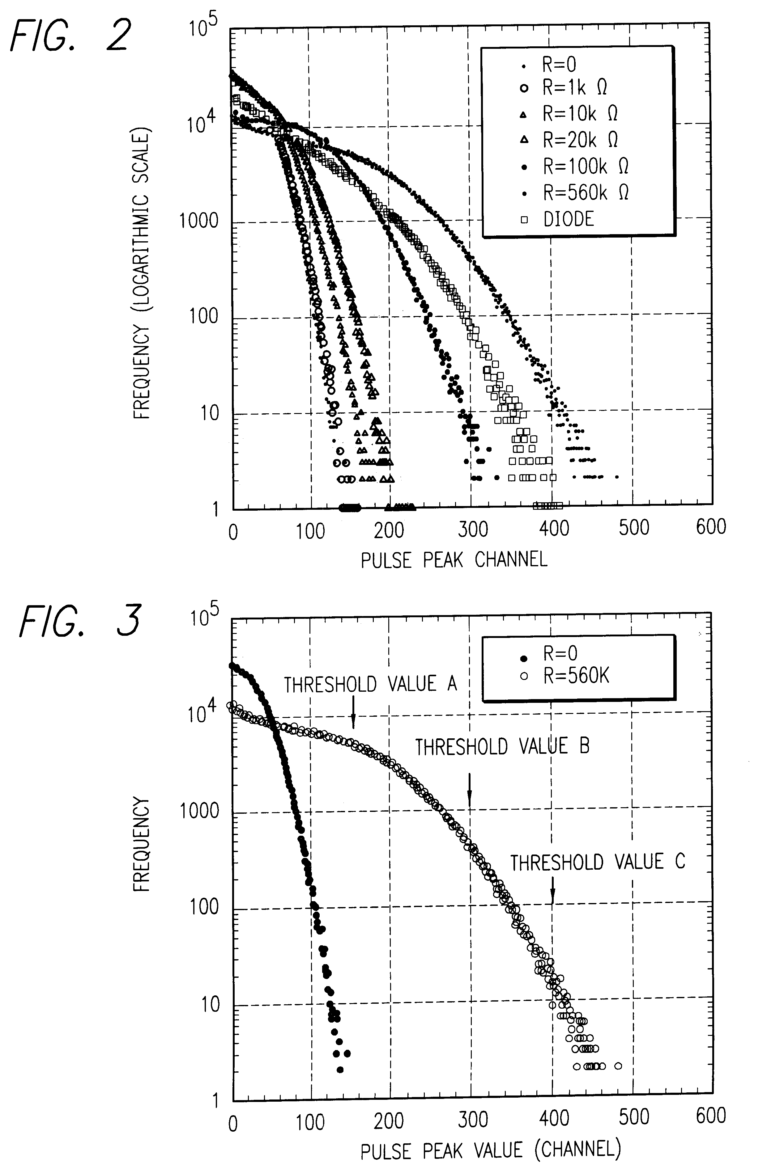
It is well known that a variety of noises are generated from a semiconductor, a conductor or a resistor when an electric current is supplied to them. These noises include thermal noises generated as a result of thermal motions of carriers and / or conduction electrons, so-called 1 / f noises that are considered to be related to the surface condition and the electrical contacts between parts, current noises that are generated when an electric current is supplied to them (1 / f noises) and shot noises that are generated due to fluctuations that arise due to the fact that the number of carriers and / or electrons is finite. According to the invention, the true random numbers are generated by utilizing the perfectly random phenomenon that are obtained by amplifying the pure thermal noises that arise when no electric current is supplied to a resistor, a semiconductor or a diode.

The square means value of the voltages produced by thermal noises is given by the formula below:

=4kRTB (formula 1),

wher...


PUM


Abstract

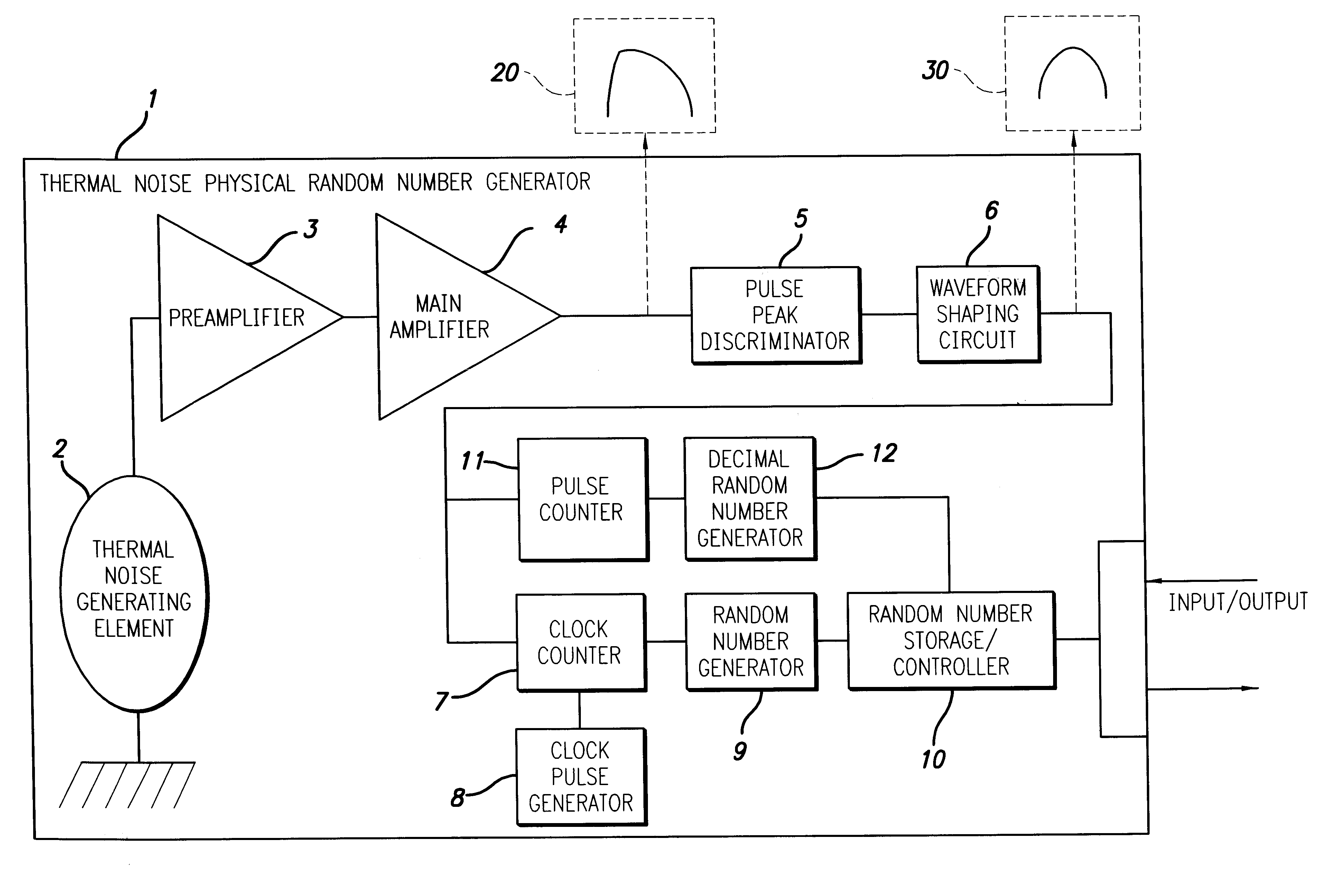
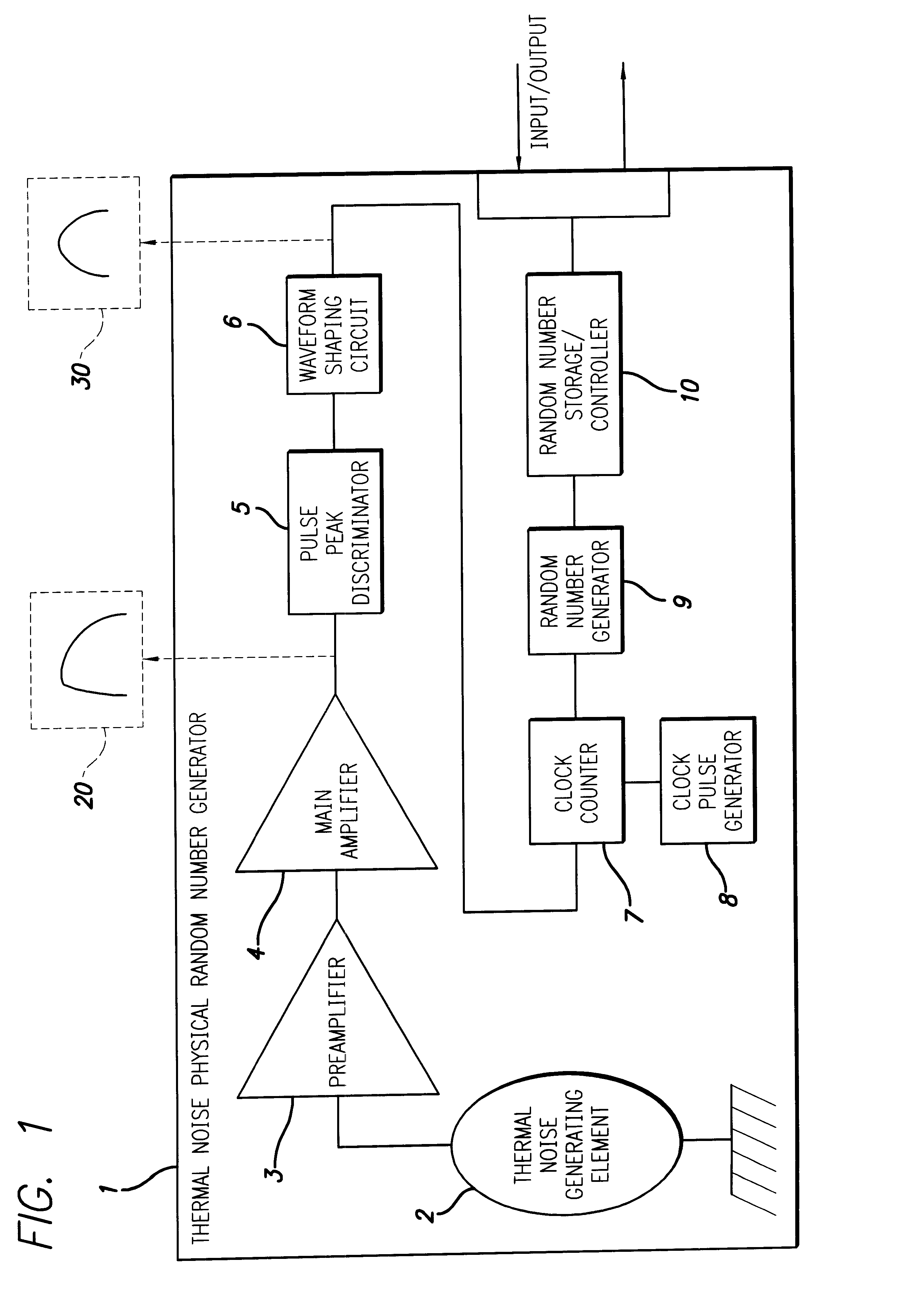
A random number generator has a simple configuration using know inexpensive electronic parts and can generate the true physical random numbers at a required generation speed. Such a random number generator can provide the true physical random numbers to any sectors of society at dramatically low cost A random pulse generator comprises a thermal noise generating element (2) having a resistor, a conductor or a semiconductor such as a diode adapted to generate thermal noises Hen no electric current is supplied to them, an analog-amplifier circuit for amplifying the irregular potential generated from the thermal noise generating element and a waveform shaping circuit (6) adapted to take out the output of the amplifier circuit as random rectangular pulse signals. A thermal noise random number generator comprises, in addition to the above components, an n-bit counter (n being an integer) for measuring the time interval between a random pulse signal output from the waveform shaping circuit (6) and the immediately succeeding random pulse signal and is adapted to output the count of the n-bit counter as natural random number.

Description

This invention relates to a physical random number generator adapted to generate the true random numbers by taking out thermal noises generated from a thermal noise generating element such as a resistor or a diode Men no electric current is supplied to the thermal noise generating element and amplifying it by means of an amplifier. A physical random number generator according to the invention can suitably be used for personal identification, coding and other purposes in computer telecommunications and mail-order business because it can perfectly eliminate frauds. A physical random number generator according to the invention is also suitable for generating the probability in various game machines.Known physical random number generating methods include those for generating random numbers by detecting a random phenomenon of nuclear decay as disclosed in Japanese Patent Applications Laid-Open Nos. 11-161473 and 11-184676 filed by the inventor of the present invention and those for gener...

Claims


Application Information

Patent Timeline
IPC IPC(8): G06F7/58H03K3/84
CPCG06F7/588
Inventor SAITO, TAKESHI
Owner L E TECH
Learn More