Planar particle imaging and doppler velocimetry system and method

a technology of doppler velocimetry and planar particle imaging, applied in the direction of instruments, devices using optical means, reradiation, etc., can solve the problems of limited optical access, poor discrimination of resolved velocity components, and limited optical access

Inactive Publication Date: 2003-04-01
U S GOVERNMENT AS REPRENTED BY THE ADMINISTATOR OF NAT AERONAUTICS & SPACE ADMINISTATION
View PDF13 Cites 43 Cited by
  • Summary
  • Abstract
  • Description
  • Claims
  • Application Information

AI Technical Summary

Problems solved by technology

If optical access points to a fluid point are not at oblique angles, poor discrimination in the resolved velocity components will result.
Unfortunately with many flow field velocity measurement platforms such as aerospace propulsion testing platforms, optical access is extremely limited.
Limited optical access is typically due to concerns regarding mismatched boundary conditions on walls or due to concerns regarding high thermal or mechanical stresses.

Method used


Image

  • Planar particle imaging and doppler velocimetry system and method
  • Planar particle imaging and doppler velocimetry system and method
  • Planar particle imaging and doppler velocimetry system and method

Examples


Embodiment Construction

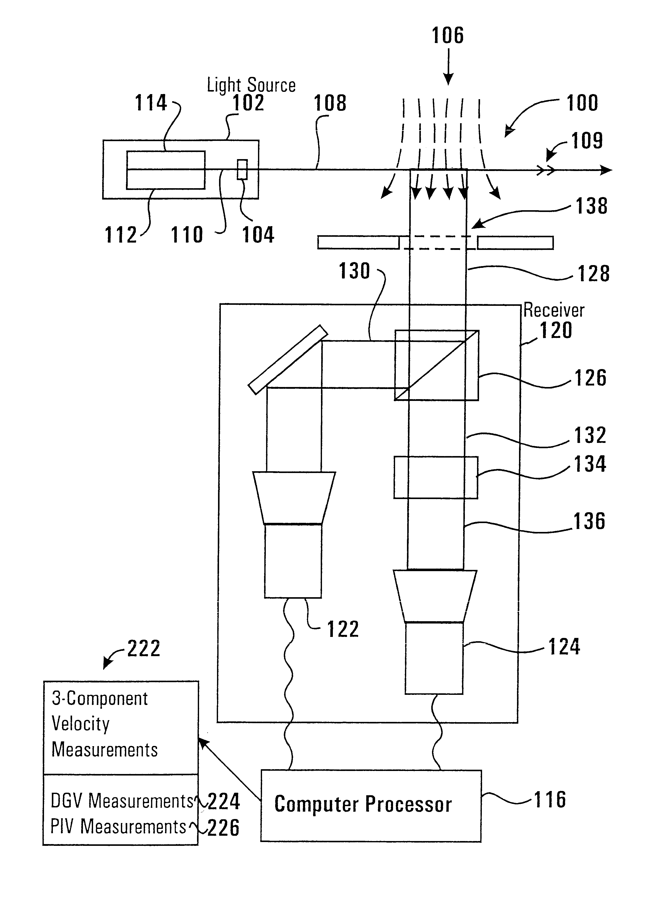
Referring now to the drawings and particularly to FIG. 4, there is shown therein a schematic view representative of a planar particle imaging and Doppler velocimetry system 100 of one exemplary embodiment of the present invention. The system includes a pulsed laser light source 102 that is operative to output pulses of light 110. In the exemplary embodiment the light source 102 includes a lens or lenses 104 which is operative to form an illuminated light sheet 108 for each pulse of laser light source 102. The laser light source 102 is positioned such that the illuminated light sheet is projected across a fluid flow 106 being measured by the system.

In one exemplary embodiment of the present invention, the light source 102 includes two lasers 112, 114 which are operatively configured to output pulses of light 110 which are coaxially aligned along a common line. As a result, the corresponding light sheets 108 formed by each pulse of each laser 112, 114 are coincident in position across...


PUM


Abstract

A planar velocity measurement system (100) is operative to measure all three velocity components of a flowing fluid (106) across an illuminated plane (108) using only a single line of sight. The fluid flow is seeded with small particles which accurately follow the flow field fluctuations. The seeded flow field is illuminated with pulsed laser light source (102) and the positions of the particles in the flow are recorded on CCD cameras (122,124). The in-plane velocities are measured by determining the in-plane particle displacements. The out-of-plane velocity component is determined by measuring the Doppler shift of the light scattered by the particles. Both gas and liquid velocities can be measured, as well as two-phase flows.

Description

This invention relates to planar velocity measurements. Specifically this invention relates to a planar velocity measurement system and method which requires only a single line of sight to measure all three velocity components of a fluid field flow across an illuminated plane.Systems for planar velocity measurers of fluid field flows are well known. Examples of planar velocity measurement techniques include particle imaging velocimetry (PIV) and Doppler global velocimetry (DGV). In both of these techniques a laser is used to illuminate a fluid flow seeded with particles. With PIV the particle positions at multiple instances in time are recorded with CCD cameras. With DGV the Doppler shift in scattered laser light by particles in the flow is measured.In general PIV is capable of providing 3-component flow field measurements using a two camera, stereo viewing configuration. An example of a PIV configuration 10 is shown in FIG. 1. Here two cameras 11, 12 view light 18 scattered from a ...

Claims


Application Information

Patent Timeline
Patent Type & Authority Patents(United States)
IPC IPC(8): G01P5/26G01P5/00G01S17/00G01S17/58G01S7/48G01S7/497G01S17/95
CPCG01P5/001G01P5/26G01S17/58G01S7/497G01S17/95Y02A90/10
Inventor WERNET, MARK P.
Owner U S GOVERNMENT AS REPRENTED BY THE ADMINISTATOR OF NAT AERONAUTICS & SPACE ADMINISTATION
Why Eureka
Try Eureka