Light receiving module and radiation detecting apparatus equipped with the same

a radiation detection and light receiving technology, applied in the direction of navigation instruments, instruments for comonautical navigation, instruments, etc., can solve the problem of radiation detection accuracy affecting the operation of the same, and achieve the effect of reducing the accuracy of radiation detection

Inactive Publication Date: 2003-04-08
HAMAMATSU PHOTONICS KK
View PDF8 Cites 16 Cited by
  • Summary
  • Abstract
  • Description
  • Claims
  • Application Information

AI Technical Summary

Problems solved by technology

Such conventional radiation detecting apparatuses however have a drawback th

Method used


Image

  • Light receiving module and radiation detecting apparatus equipped with the same
  • Light receiving module and radiation detecting apparatus equipped with the same
  • Light receiving module and radiation detecting apparatus equipped with the same

Examples


first embodiment

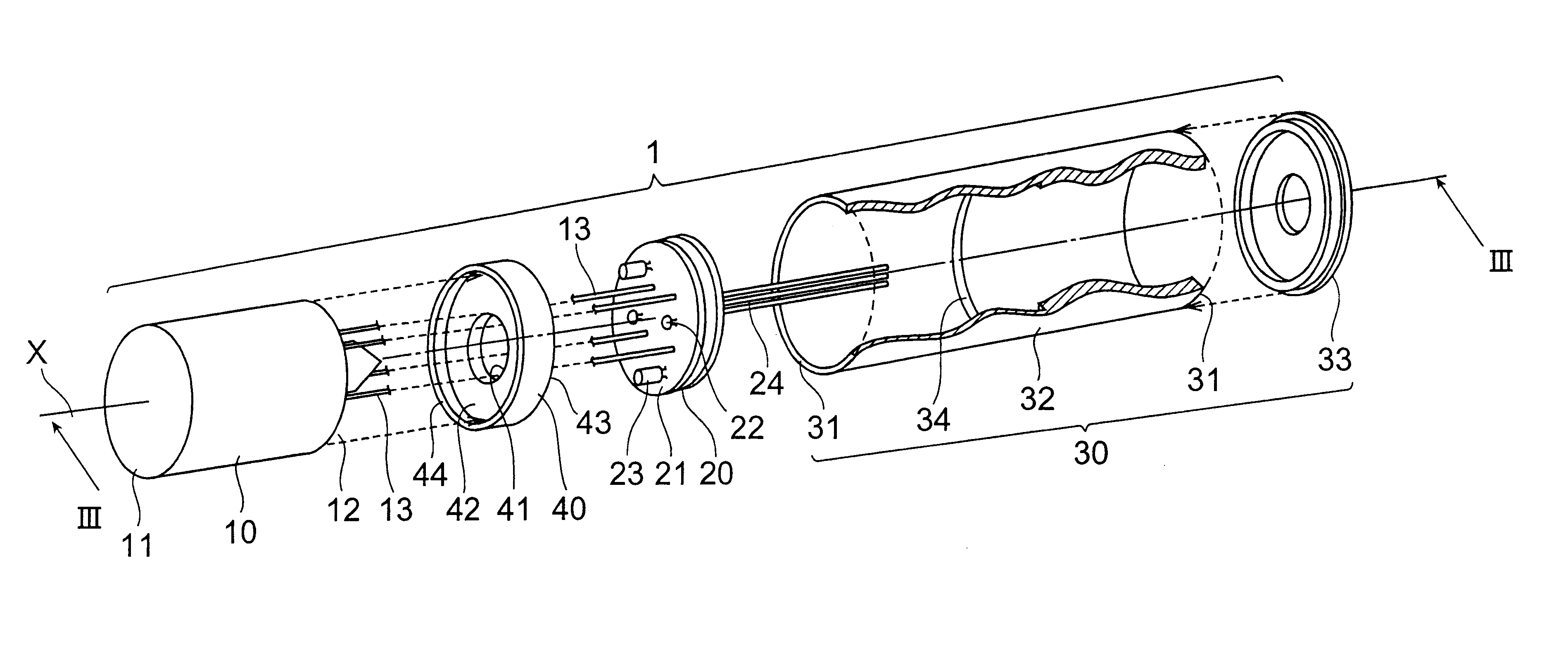
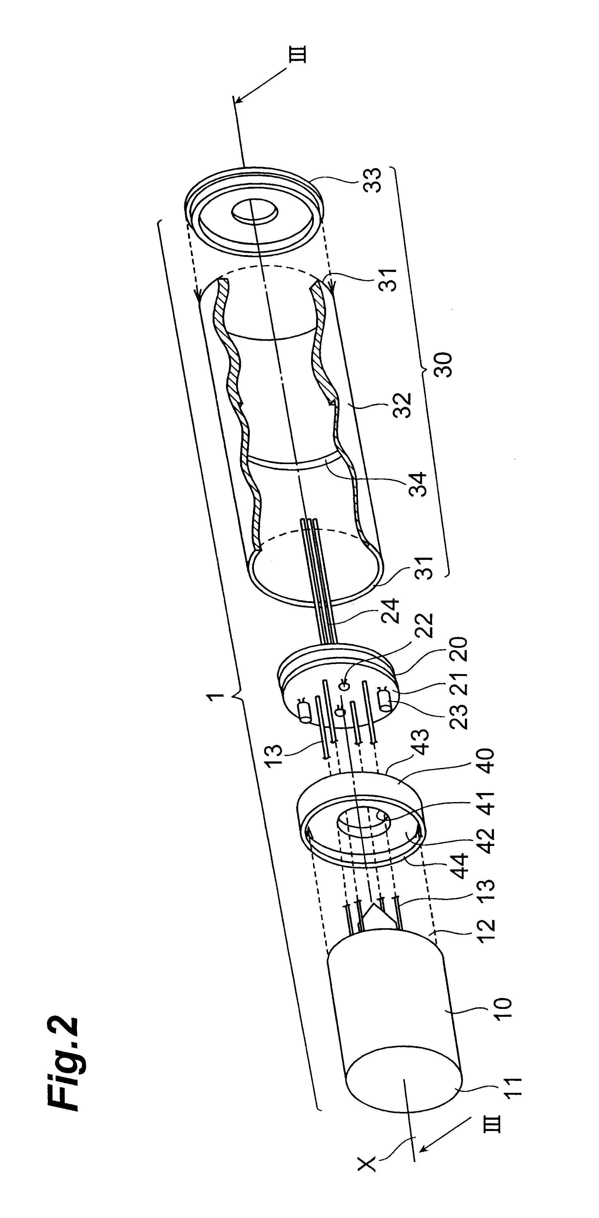
FIG. 2 is a view of an assembly step showing the light-receiving module according to the present invention. FIG. 3A is a cross sectional view of the light-receiving module taken along the line III--III in FIG. 2.

In FIGS. 2 and 3A, the light-receiving module 1 comprises a photomultiplier 10, a bleeder circuit board 20, a module case 30, and a stopper 40 which all are aligned along the center axis X of the module case 30.

The photomultiplier 10 is of so-called a head-on type having a faceplate 11 for receiving light and a stem 12 opposing each other. The photomultiplier 10 is contemplated particularly in its photoelectric surface, dynode, and electrode structure (these three are not shown) for providing its performance when operated under high-temperature, vibrating conditions.

The bleeder circuit board 20 supplies dynodes in the photomultiplier 10, not shown, with a voltage having a potential gradient. The bleeder circuit board 20 has resistors 22 and capacitors 23 connected on a disk-...

second embodiment

FIG. 11 is a cross sectional view showing a structure of a radiation detecting apparatus 50 equipped with the light-receiving module 1 of the

As shown, while the photomultiplier 10 of the light-receiving module 1 has its faceplate 11 and stem 12 arranged not in parallel, the stem 12 and the contact surface 42 of the stopper 40 are controlled to align the faceplate 11 in parallel with the opening 31 of the module case 30 and simultaneously the stem 12 is seated at its rim portion directly on the contact surface 42 of the stopper 40.

As a result, the force applied by the spring 53 is distributed evenly onto the entire surface of the faceplate 11, hence ensuring a higher level of the coupling between the light-receiving module 1 and the scintillator 52. Also, the stem 12 is prevented from locally receiving a convergence of stress, thus minimizing the damage to the photomultiplier 10.

While the light-receiving module 1 of the second embodiment provides the same effect as of the first embod...


PUM


Abstract

The present invention relates to a light-receiving module of a heat-resistant, vibration-resistant type for use in petroleum exploration or the like, and a radiation detecting apparatus equipped with the light-receiving module. The light-receiving module comprises a photomultiplier having a faceplate and a stem opposing each other, a bleeder circuit board provided so as to sandwich the stem together with the faceplate and electrically connected to the photomultiplier, a module case provided so as to accommodate the photomultiplier and the bleeder circuit board, said module case having an opening for exposing the faceplate of the photomultiplier, a step provided on an inner surface of the module case, and a stopper seated on the step, defining the position of the photomultiplier in the module case.

Description

1. Field of the InventionThe present invention relates to a light-receiving module of a heat-resistant, vibration-resistant type for use in petroleum exploration and a radiation detecting apparatus equipped with the same.2. Related Background ArtThe petroleum exploration is commonly carried out, as shown in FIG. 1, with a probe 94, which comprises a radiation source 90 and a radiation detecting apparatus 92 mounted therein, by lowering into a drilled or drilling well bore 96 and operated to measure and analyze scattered rays or a level of natural radiation derived from a stratum 98. The radiation detecting apparatus 92 for use in the petroleum exploration is operated under hostile conditions with a higher temperature (150 to 200.degree. C.) and an unfavorable degree of vibration in such an oil well drilled deeply under the ground or in a drilling module for the petroleum drilling.Such conventional radiation detecting apparatuses however have a drawback that its accuracy for detectin...

Claims


Application Information

Patent Timeline
IPC IPC(8): G01T1/00G01T1/20H01J43/28H01J43/00
CPCH01J43/28G01T1/20
Inventor ISHIZU, TOMOHIROMORITA, TETSUYA
Owner HAMAMATSU PHOTONICS KK
Why Eureka
Try Eureka