Mounting device for an optical element

a technology of mounting device and optical element, which is applied in the direction of mounting, microlithography exposure apparatus, instruments, etc., can solve the problems of inability to make the joint too soft and inability to achieve effective compensation

Inactive Publication Date: 2003-04-22
CARL ZEISS SMT GMBH
View PDF6 Cites 70 Cited by
  • Summary
  • Abstract
  • Description
  • Claims
  • Application Information

AI Technical Summary

Benefits of technology

A ratio in which the two-wave components of deformation of the optical surface of the optical element cancel one another out is found by a configuration, according to the invention, of the gear elements and by an appropriate selection of the joining points of the optical element or of an optical assembly in the case of one or more of the three load instances, that is to say an axial base point displacement, a radial base point displacement and a tangential base point rotation for the axial forces, radial forces and the tangential moments at each joining point. Assuming that the total stiffnesses remain the same in all design variants of the gear elements, in the case of complete compensation of the two-wave deformation components a point is reached at which the aspherical component of the deformation is close to a minimum as a function of the load ratios. The minimum of the aspherical deformation can then be found easily by means of small corrections in the load ratio provided by the gear elements.
Moreover, it is possible by means of the type of mounting described to minimize deformations which are caused by bearing reactions which are in equilibrium with accelerating forces such as, for example, the weight force. In other words, this means that acceleration-induced deformations of the optical surface are likewise minimized.
The compensation effect is provided according to the invention for disturbances which lead to a variation in the relative position and the orientation of the base points of the gear elements. The same also holds for variations in the joining loads at the top points of the gear elements which are caused by accelerations.

Problems solved by technology

However, in this case there is a problem that it is impossible to make the joint too soft for example because of the natural frequency requirements.
If the joining point moves very far inward, the deformation distributions of the individual loads are dissimilar starting from a specific limit, and so effective compensation is no longer possible.

Method used


Image

  • Mounting device for an optical element
  • Mounting device for an optical element
  • Mounting device for an optical element

Examples


Embodiment Construction

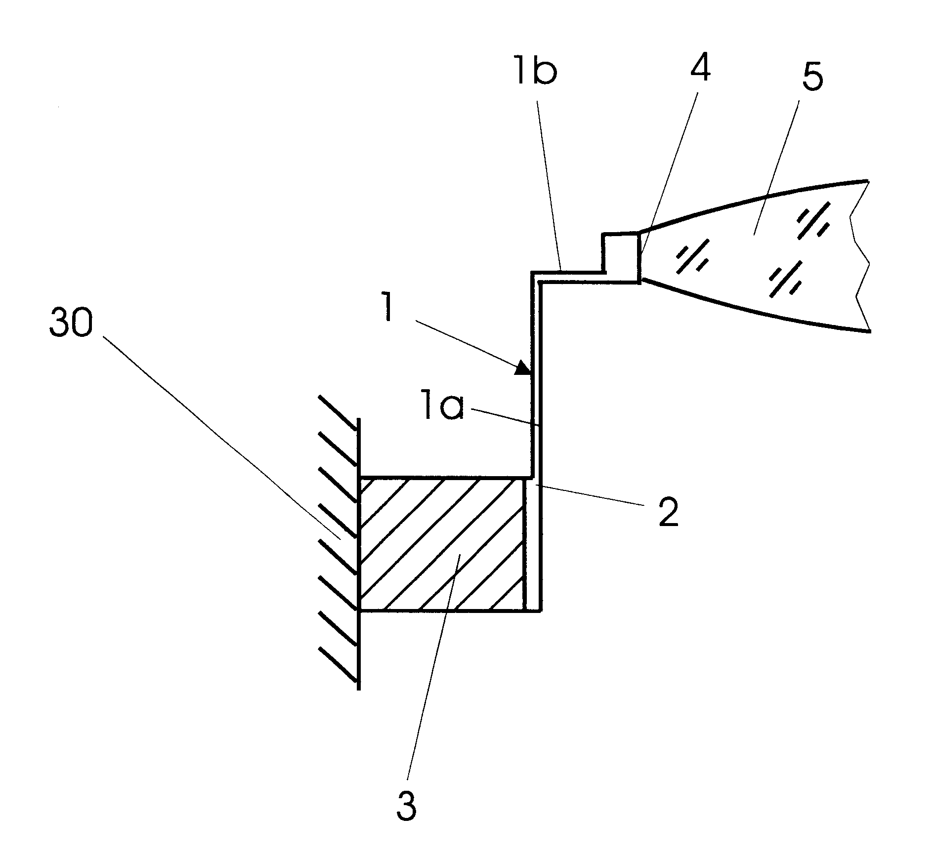
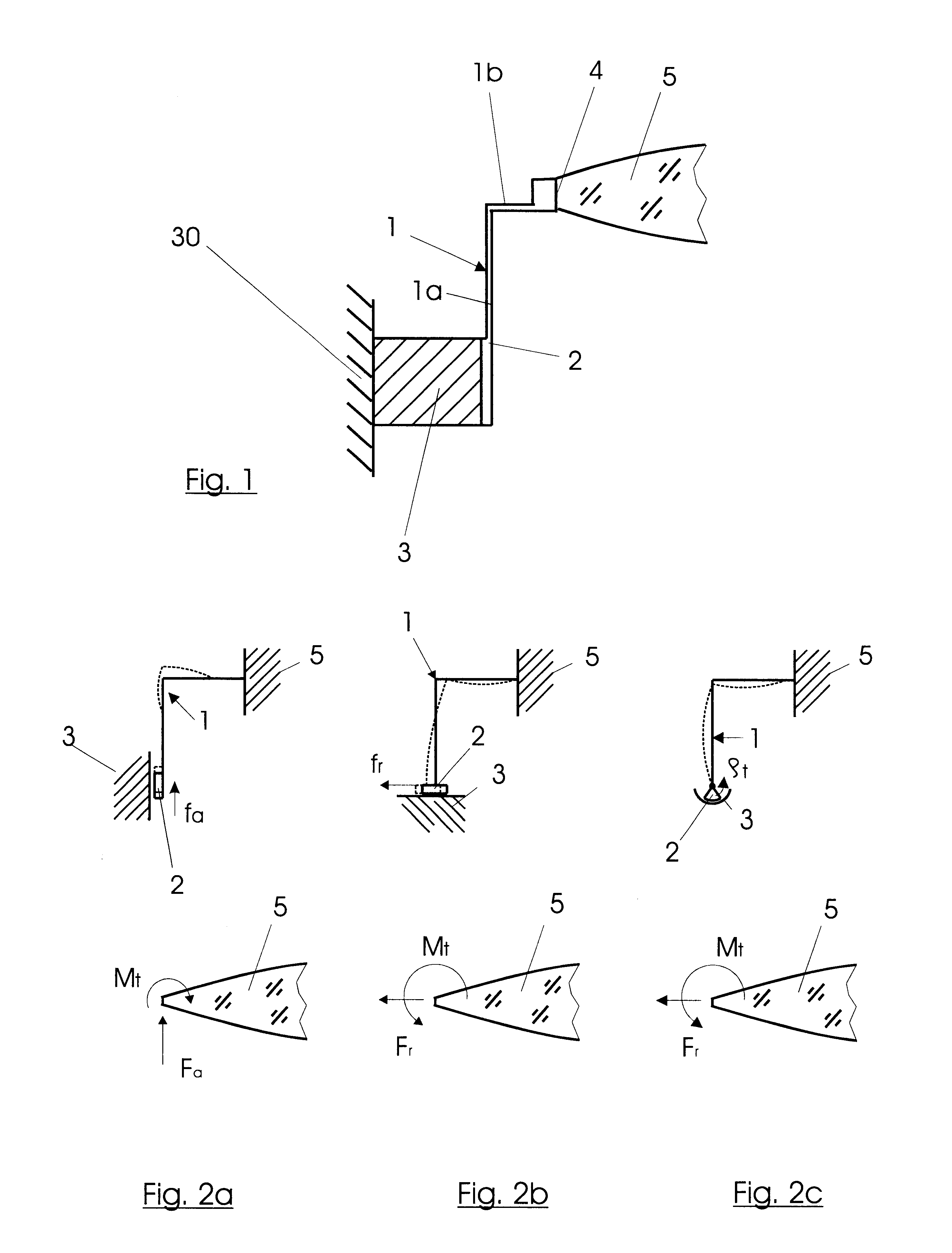
FIG. 1 shows, in a representation of the principle, the spring geometry of a gear element 1 which is designed with an axially situated torsion spring 1a and a radial torsion spring 1b, and thereby forms an angular shape. A plurality of gear elements 1 arranged in a fashion distributed uniformly over the circumference are in each case connected to a support member 3 at one end via base points 2. The support member 3 is connected (in a way not shown in more detail) to an external mounting structure 30 or an assembly which, for example, forms a lens for a semiconductor lithography exposure system. Via the radially situated torsion spring 1b and a top point 4, in each case, a joint to an optical element 5, which is a lens in the case of the exemplary embodiments discussed below, made at the other end of the gear element 1.

The various load instances and main loads resulting therefrom on the optical element 5 may be seen in FIGS. 2a, 2b and 2c. An axial displacement of the base point 2 is...


PUM

PropertyMeasurementUnit
angleaaaaaaaaaa
angleaaaaaaaaaa
angle α1aaaaaaaaaa

Abstract

A mounting device for an optical element in an assembly has a support member 3 with two or more gear elements 1. The support member 3 is connected, on the one hand, to an external mounting structure 30 and, via base points 2, to the gear elements 1. Via top points, the gear elements 1 are connected to the optical element 5 directly, or are connected to the optical element 5 indirectly via a mount 5' arranged therebetween. The top points 4 of the gear elements 1 are located in planes of symmetry of the optical element 5 which are defined by the axial axis and a radial axis of the optical element 5. The gear elements 1 are arranged and dimensioned such that in the event of disturbing influences a compensation effect is produced with regard to the deformation of the optical surface of the optical element 5. The compensation effect is provided when the RMS value of the sum of those partial deformations of the optical surface of the optical element 5 which are caused by an axial force, a radial force and a tangential element at an arbitrary top point 4 of a gear element 1 is smaller by at least the factor 2 than the greatest RMS value of one of the three said partial deformations.

Description

This application relates to and claims priority to corresponding German Patent Application No. 100 53 899.1 filed on Oct. 31, 2000.1. Field of the InventionThe invention relates to a mounting device for an optical element in an assembly. More specifically the invention relates to a micro lithographic projection exposure objective having a device for mounting an optical element.2. Description of the Related ArtMounting techniques are known for rotationally symmetrical optical elements, in the case of which the optical element is connected to a mounting member via a number of elastic elements. Elastic elements are permanently connected, for example by bonding, to the optical element in the region of the outer edge of the latter, and distributed uniformly over the circumference. The elastic elements are mostly designed as spring arms with an axially and a radially situated bent part. In the case of movements of the base points of the spring arms relative to the optical element, such as...

Claims


Application Information

Patent Timeline
Patent Type & Authority Patents(United States)
IPC IPC(8): G02B7/02G02B7/00G03F7/20H01L21/027
CPCG02B7/026
Inventor DIEKER, THOMAS
Owner CARL ZEISS SMT GMBH
Why Eureka
Try Eureka