Turbinate heat sink

a heat sink and turbinate technology, applied in the field of heat sinks, can solve the problems of deteriorating the stability and operation of the cpu, obstructing airflow, radial fins, etc., and achieve the effect of enhancing heat convection and minimizing resistance to incoming forced

Inactive Publication Date: 2003-04-22
HON HAI PRECISION IND CO LTD
View PDF4 Cites 39 Cited by
  • Summary
  • Abstract
  • Description
  • Claims
  • Application Information

AI Technical Summary

Benefits of technology

Accordingly, an object of the present invention is to provide a heat sink which minimizes resistance to incoming forced airflow and outgoing airflow, and thus enhances heat convection.
To achieve the above object, a heat sink comprises a circular base, a plurality of fins and a central post. The base is adapted to be in thermal contact with an electronic device, to remove heat therefrom. The post extends from a top surface of the base. The post has a first surface connected to the top surface and a second surface dimensioned according to a rotary heat sink fan to be attached thereon, to minimize blockage of cooling air emitted from the fan. The post also has a concave side surface connected between the second surface of the post and the top surface of the base, for directing airflow toward an exterior of the heat sink and minimizing resistance to incoming airflow. The fins are identical in height to the post, so that cooling air emitted by the fan passes directly into the heat sink. The fins are curved, aligned and spaced from each other at uniform intervals corresponding to directions of airflow generated from the fan. This minimizes resistance to cooling air entering and exiting the heat sink.

Problems solved by technology

This can deteriorate the stability and operation of the CPU.
When such air enters a conventional heat sink, it strikes the radial fins, rebounds, and also creates obstructing airflow.
Additionally, part of the air emitted by the fan strikes a top surface of the base, rebounds back toward the fan, and creates obstructing airflow.
All this retards air from entering the heat sink and exiting the heat sink, and thus reduces the efficiency of forced convection.

Method used


Image

  • Turbinate heat sink
  • Turbinate heat sink
  • Turbinate heat sink

Examples


Embodiment Construction

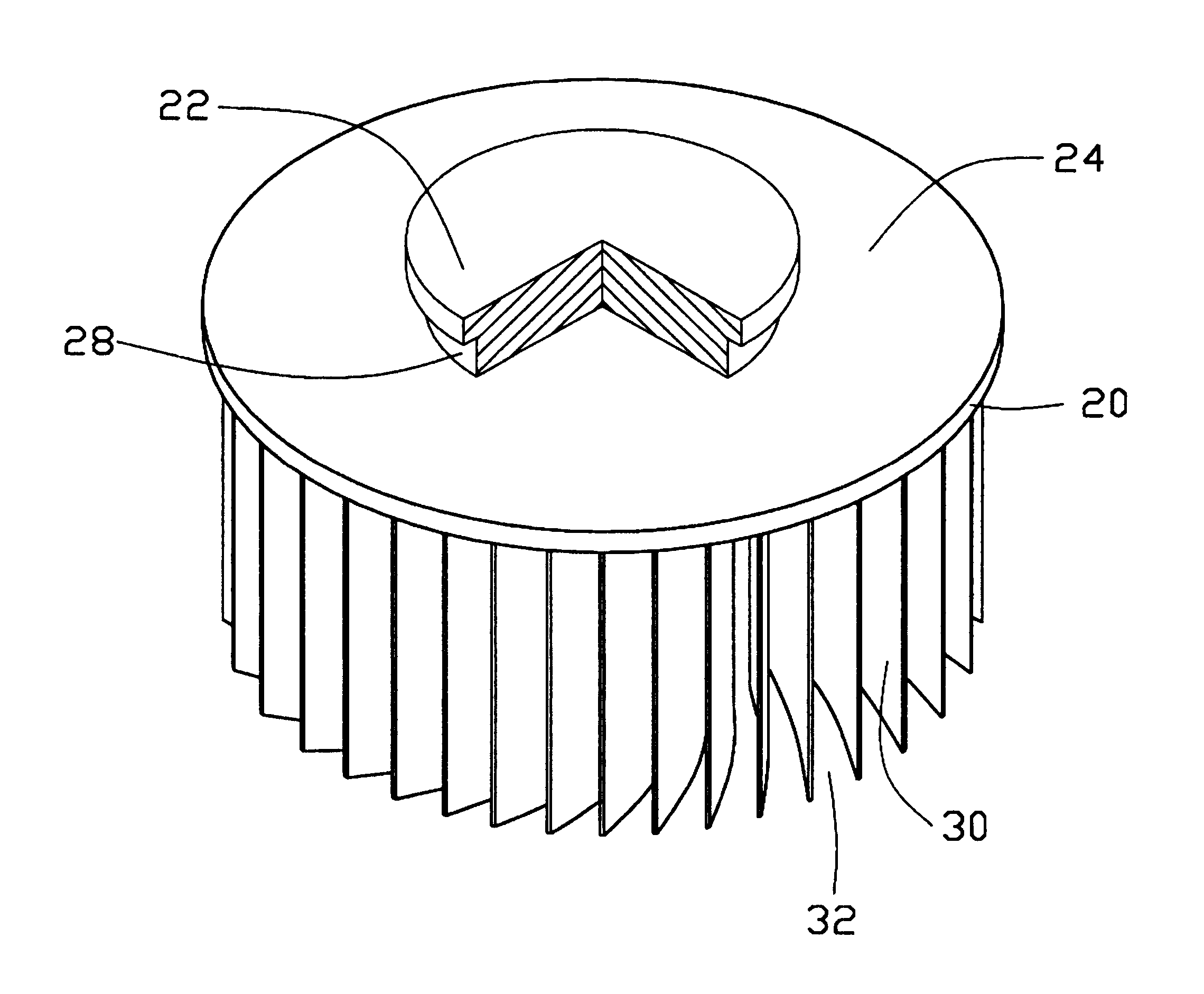
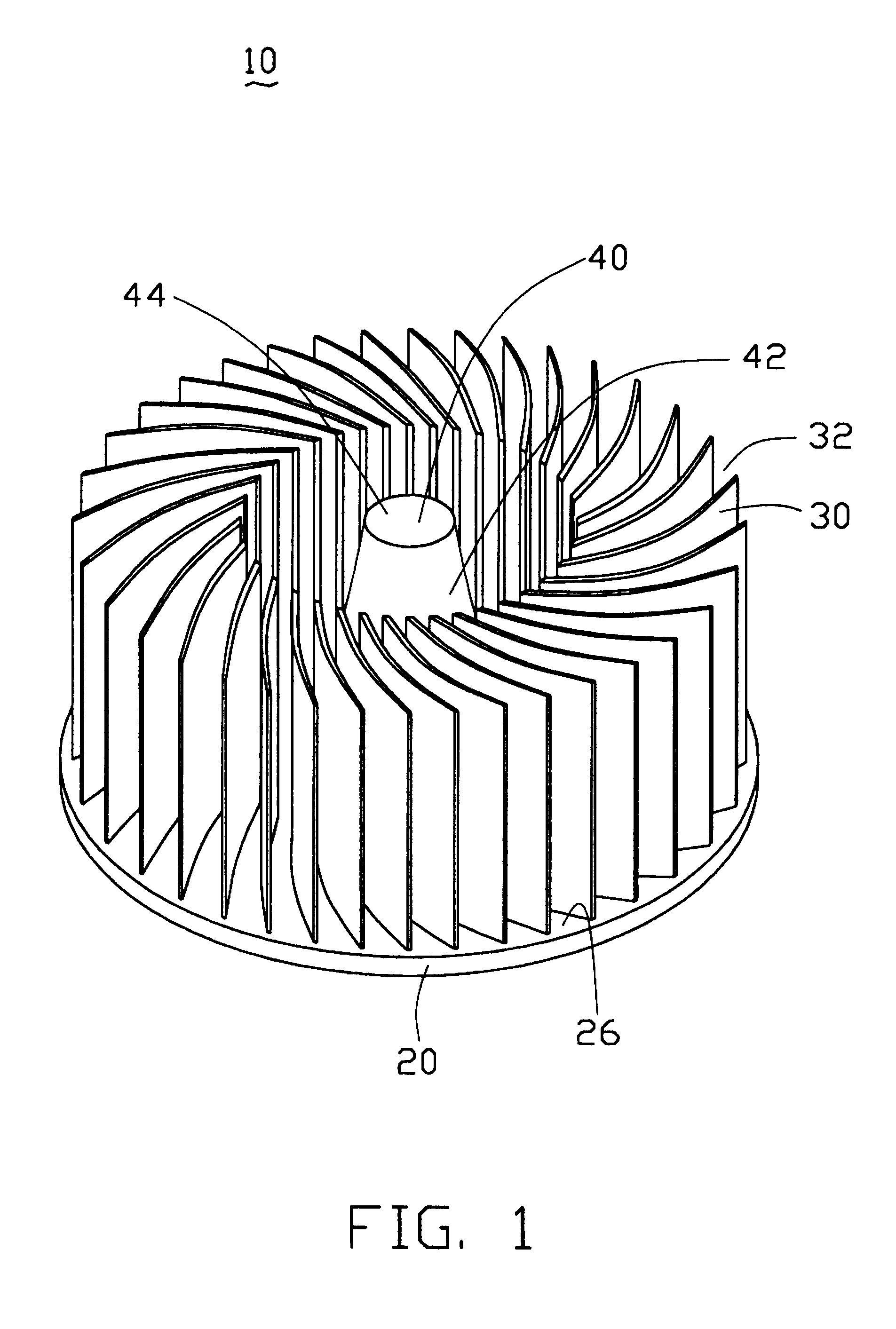
FIG. 1 shows a heat sink 10 in accordance with a preferred embodiment of the present invention, for removing heat from an electronic device such as a central processing unit (CPU) (not shown). The heat sink 10 is formed as a single unit. The heat sink 10 comprises a circular base 20, a plurality of fins 30, and a central post 40.

The post 40 extends upwardly from a top surface 26 of the base 20, and is coaxial with the base 20. The post 40 includes a first surface (not labeled), a second surface 44 and a concave side surface 42. The first and second surfaces are substantially round. The first surface is connected to the top surface 26 of the base 20. The second surface 44 is smaller than the first surface, dimensioned according to a rotary heat sink fan (not shown) to be attached thereon. The concave side surface 42 is connected between the first and second surfaces for minimizing resistance to incoming airflow and directing airflow toward an exterior of the heat sink 10.

The fins 30 ...


PUM


Abstract

A heat sink (10) includes a circular base (20), a plurality of fins (30), and a central post (40). The base is adapted to be in thermal contact with an electronic device, to remove heat therefrom. The post extends from a top surface (26) of the base. The post has a first surface connected to the top surface and a second surface (44) dimensioned according to a heat sink fan to be attached thereon. The post also has a concave side surface (42) between the second surface of the post and the top surface of the base, for directing airflow. The fins are identical in height to the post. The fins are curved, aligned and spaced from each other at uniform intervals corresponding to directions of airflow generated from the fan. These minimize resistance to cooling air entering or exiting the heat sink.

Description

BACKGROUND OF THE INVENTION1. Field of the InventionThe present invention relates to a heat sink, and more particularly to a heat sink having components with minimal resistance to forced airflow.2. Related ArtIn contemporary computers, the most common kind of heat-generating electronic device is a Central Processing Unit (CPU). The CPU is the most important controller of electronic signals in a typical computer. A great deal of heat is generated by contemporary CPUs during normal operation. This can deteriorate the stability and operation of the CPU. Thus heat must be removed from the CPU quickly, to ensure proper operation of the computer. Oftentimes, a heat sink is mounted on a top surface of the CPU to remove heat therefrom.A conventional heat sink includes a base positioned in contact with a CPU, and a plurality of fins radially extending from a center of the base. A rotary heat sink fan is frequently attached to a top of the heat sink, for providing forced airflow and facilitat...

Claims


Application Information

Patent Timeline
Patent Type & Authority Patents(United States)
IPC IPC(8): H01L23/34H01L23/467
CPCH01L23/467H01L2924/0002H01L2924/00
Inventor CHO, ERICLAI, CAREYLIN, MARK
Owner HON HAI PRECISION IND CO LTD
Why Eureka
Try Eureka