Laser pet toy

a technology of lapser and toy, applied in the field of improved, can solve the problems of unused toy, safety issue, pain, etc., and achieve the effect of keeping the interest of the pet and a safer environment for the pet and its owner

Inactive Publication Date: 2003-05-06
LORENZ EILEEN LISA
View PDF11 Cites 14 Cited by
  • Summary
  • Abstract
  • Description
  • Claims
  • Application Information

AI Technical Summary

Benefits of technology

It is another object of the invention to provide a stand alone laser pet toy designed to keep the interest of the pet without causing soreness and strain to the owner's ligaments.
It is another object of the invention to provide a stand alone pet toy which can maintain its position out-of reach of the pet while the device is engaging the pet in exercise activity thus creating a safer environment for the pet and its owner.
It is another object of the invention to provide a laser pet toy that can exhibit a random range of motion yet still be manufactured at a low cost thereby making the device economically available to consumers.

Problems solved by technology

Unfortunately, to operate most pet toys, the owner must use repetitive motions over long periods of time to keep the interest of the cat.
These repeated movements over an extended time can cause soreness, strain and even pain for the owner's fingers, wrists, elbow and hand.
Since such movement is strenuous and hurtful to the owner's ligaments, the cat's activity is usually stopped long before the cat wants the activity to end.
This results in an unused toy.
Other patent disclosures do address the issue of providing continuous motion without straining the owner's ligaments rather effectively, but these devices require the cat to play with the actual toy itself which becomes a safety issue to both pet and owner.
Given that a cat's natural predatory instinct includes pouncing and jumping on its prey until its prey is lifeless, the toy is usually broken.
These small broken pieces may easily cause a choking hazard to the pet.
This will result in a broken toy.
Another safety concern arises when the device is left stationed on the floor causing the owner to trip and fall over it.
U.S. Pat. No. 5,934,223 does address the issue of providing continuous motion without causing strain to the owner's ligaments, however, the device is designed to project an image primarily onto the ceiling and walls rather than the floor which does not take into consideration the natural instincts of a cat.
While this may provide exercise and amusement to the cat, the owner will be frustrated and unhappy.
This will result in an unused toy.
Another limitation to U.S. Pat. No. 5,934,223 is its high cost to manufacture with regard to its materials, especially the computer chip or integrated circuit.
Yet another limitation to U.S. Pat. No. 5,934,223 is that the only pattern it provides is a circular motion, whether it be on the ceiling, wall or floor.
Each of these disclosures is subject to the limitations discussed above, thereby making none of the prior art pet toys entirely satisfactory.

Method used


Image

  • Laser pet toy
  • Laser pet toy
  • Laser pet toy

Examples


second embodiment

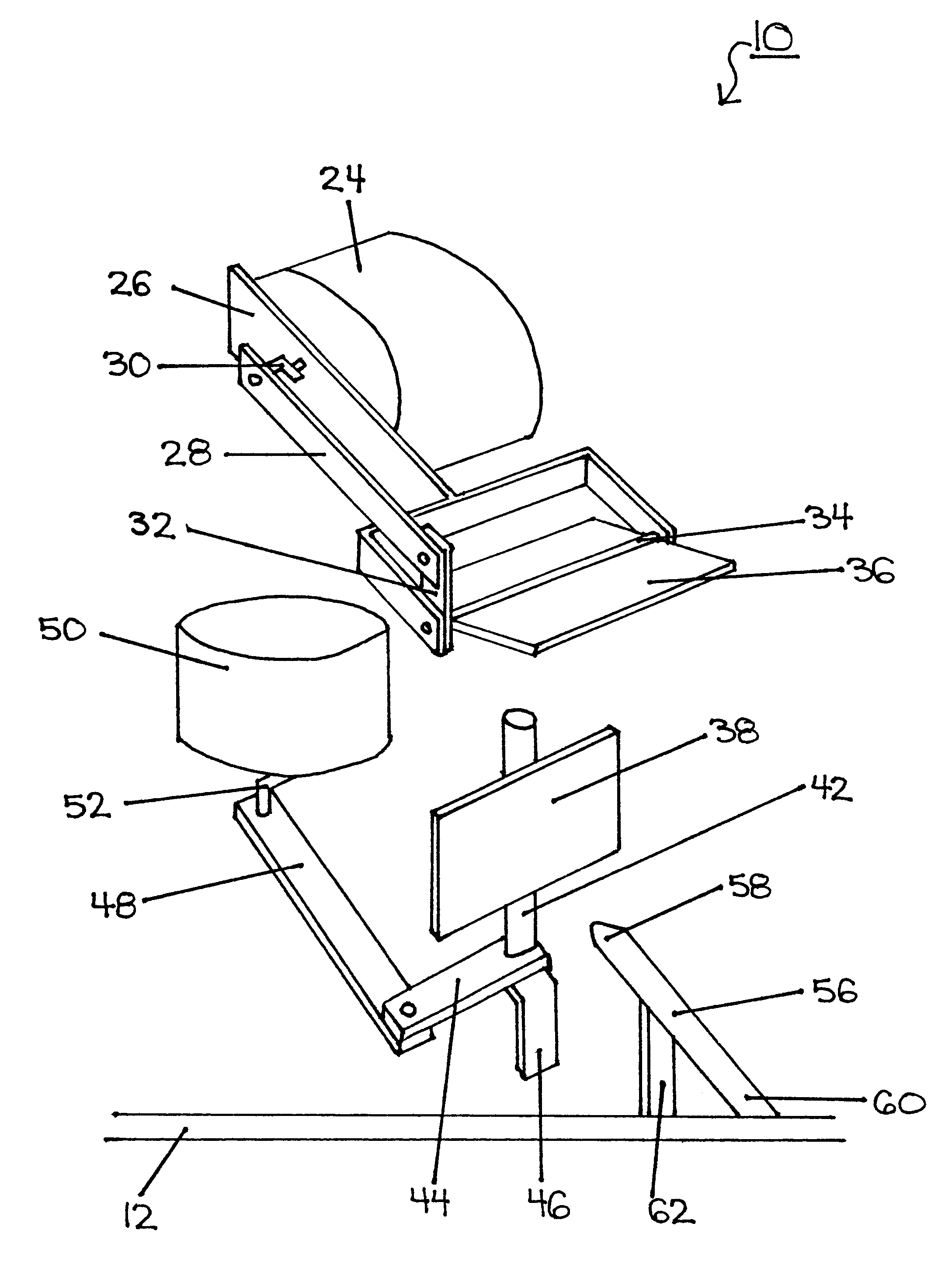
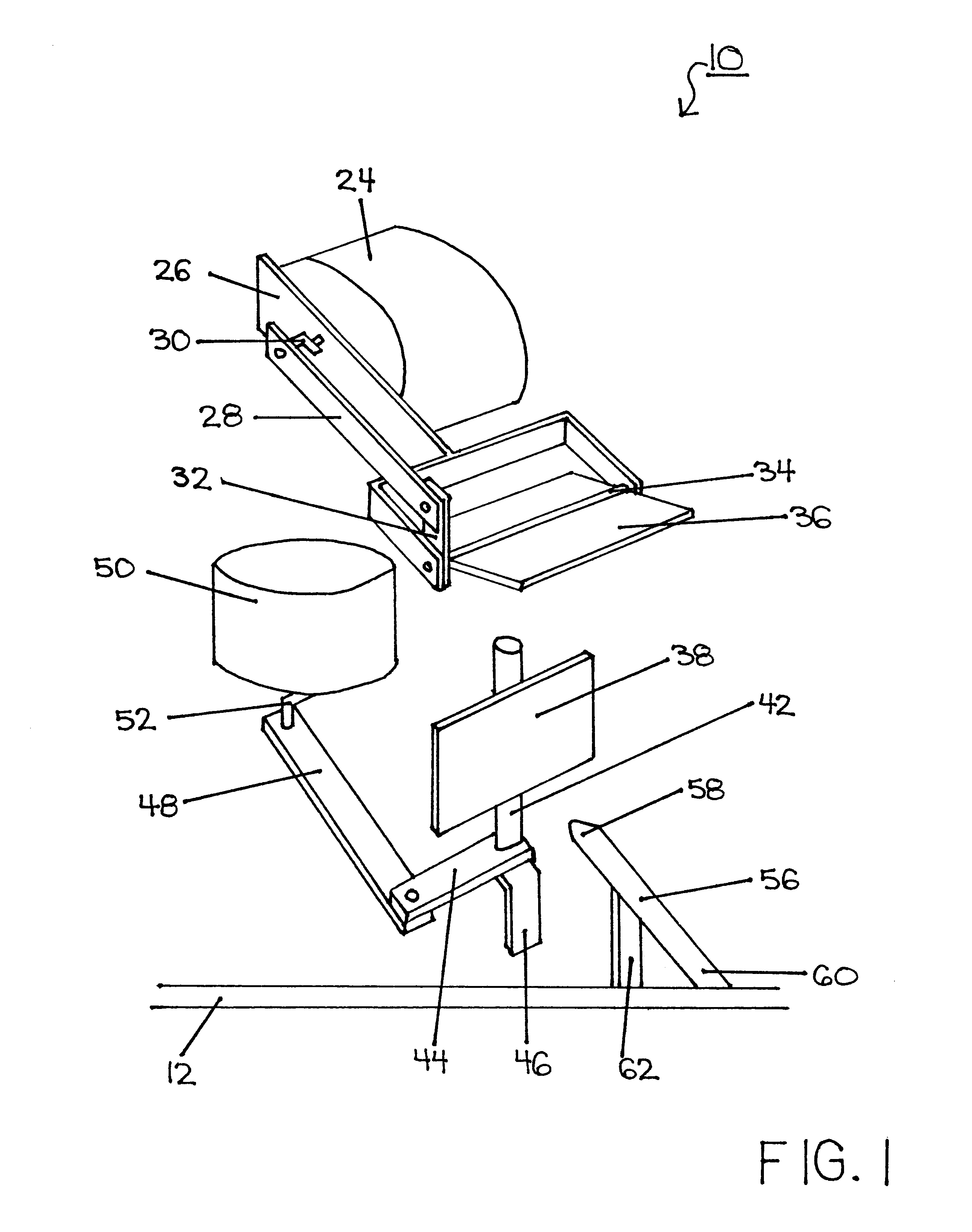
In a second embodiment, as shown in FIG. 4, a mirror 102 is mounted at an angle to a bracket 104 by gluing or any other type of fastener. The bracket 104 is mounted lengthwise to a shaft 106 by gluing or any other type of fastener. The lower end of shaft 106 is connected about perpendicular to the first end of arm 108 by glue or any other type of fastener. In addition, the lower end of shaft 106 is also connected to a bracket 110 by means of a pin or any other type of fastener. The second end of arm 108 is connected to the first end of arm 112 by a pin or any other type of fastener. The second end of arm 112 is connected to the first end of arm 116 by a crank arm 114. The second end of arm 116 is connected to a motor 118 by a crank arm 120. The motor 118 is connected to a motor bracket 122 by screws, however, gluing or other fasteners could also be used. A crank arm 120 connects the motor 118 to the first end of arm 124. The second end of arm 124 is connected about perpendicular to ...

third embodiment

In a third embodiment, as shown in FIG. 5, a motor 302 is connected to the first end of arm 306 by a crank arm 308. The second end of arm 306 is connected about perpendicular to the first end of arm 310 by a pin or any other type of fastener. The second end of arm 310 is connected about perpendicular to the first end of a shaft 312 by gluing or any other type of fastener. In addition, the first end of shaft 312 is also connected to a bracket 304 by means of a pin or any other type of fastener. The second end of shaft 312 is connected to a bracket 304 by means of a pin or any other type of fastener. A mirror 314 is fastened lengthwise to the shaft 312 by gluing or any other type of fastener.

A laser source 330 is mounted to a bracket 316 by gluing or any other type of fastener. The laser source 330 is comprised of a laser emitting end 332 and a power receiving end 334 which emits a laser beam when activated. The laser emitting end 332 must be positioned so that the laser beam reflects...

fourth embodiment

The fourth embodiment, as shown in FIGS. 6-7, is different from the hereinabovedescribed embodiments such that the device does not contain mirrors. The laser source 404 moves by the same plurality of means as the heretoforementioned embodiments except the beam reflects directly through the transparent window 402 onto the floor. The fourth embodiment would be extremely attractive to elderly cats who still need exercise, but cannot sustain the high level of excitement and activity of the preferred embodiment.

As shown in FIGS. 6-7, laser source 404 is mounted on the first end of bracket 410 by gluing or any other type of fastener. The bracket 410 is mounted lengthwise to a shaft 412 by gluing or any other type of fastener. The lower end of shaft 412 is connected about perpendicular to the first end of arm 414 by glue or any other type of fastener. In addition, the lower end of shaft 412 is also connected to the first end of bracket 416 by means of a pin or any other type of fastener. T...


PUM


Abstract

An improved laser pet toy that entertains pets, especially cats. The pet toy comprises a housing containing a laser source which projects a laser beam into a mirror. In turn, the mirror forecasts the beam through a transparent window set in the housing and projects the beam onto an opaque surface. The random movement of the beam is provided by the motion of the pivoting mirrors which is driven by a motor and a plurality of arm members.

Description

1. Field of InventionThe present invention relates generally to an improved laser pet toy for the exercise and amusement of a pet.2. Description of the Prior ArtMany pet toys involve motion because it is a known fact that pets, particularly cats, are attracted to moving objects. It is also a known fact that cats are attracted to LASER (light amplification by stimulated emission of radiation) beams. Unfortunately, to operate most pet toys, the owner must use repetitive motions over long periods of time to keep the interest of the cat. These repeated movements over an extended time can cause soreness, strain and even pain for the owner's fingers, wrists, elbow and hand. Prior art of this type is described in U.S. Pat. No. 5,443,036.To operate the laser pet toy disclosed in U.S. Pat. No. 5,443,036 the owner must continuously press the trigger switch with his / her fingers while, at the same time, move his / her hand, wrist and elbow in a repeated motion so that the cat will chase the laser...

Claims


Application Information

Patent Timeline
Patent Type & Authority Patents(United States)
IPC IPC(8): A01K15/00A01K15/02
CPCA01K15/025
Inventor LORENZ, EILEEN LISA
Owner LORENZ EILEEN LISA
Why Eureka
Try Eureka