Lamp driving topology

a topology and driving technology, applied in the field of multiple load driving systems, can solve problems such as difficult current control in this topology

Inactive Publication Date: 2003-05-06
O2 MICRO INT LTD
View PDF2 Cites 119 Cited by
  • Summary
  • Abstract
  • Description
  • Claims
  • Application Information

AI Technical Summary

Benefits of technology

The voltage required to strike Lamp2 is approximately equal to the voltage to strike Lamp1, e.g., 1500 Vrms. Since Lamp1 is already struck, there is an operational voltage of approximately 800 Vrms across the network 14. Accordingly the controller needs to supply an additional striking voltage for Lamp2. This striking voltage is the voltage across networks 14 and 16, i.e., the voltage is (1500.sup.2 +800.sup.2), or approximately 1700V. The numerical examples provided above assume a purely reactive load in the phased low impedance network 16. Thus, instead of needing to supply 3000 Vrms to strike lamps connected in series, the system 10 of the present invention significantly reduces the voltage requirements of the transformer and system components.
The impedance difference between network 14 and network 16 ensures a desired striking sequence. In the exemplary system 10 described above, Lamp1 strikes first, with a return path through network 16. Thus, as a general statement, the impedance value of network 16 is selected to ensure a return path for Lamp1. The impedance value is also a function of operating frequency, and thus may be changed according to the frequency characteristics of the system 10. To ensure a striking sequence between Lamp1 and Lamp2, qualitatively the resistance values of the two networks is selected such that network 14 initially receives a majority of the voltage delivered by the transformer. The larger the majority (i.e., the larger the resistance values between networks 14 and 16) means the less voltage that must be developed by the transformer initially. The phase difference between network 14 and network 16 permits the present invention to utilize Eq. 1 to operate two lamps connected in series without requiring double the voltage output from the transformer.

Problems solved by technology

Also, current control in this topology is difficult since the current conditions of each lamp must be monitored.
This, obviously is untenable since most transformers are incapable of providing 3000 Vrms for striking, or are prohibitively expensive.

Method used


Image

  • Lamp driving topology
  • Lamp driving topology
  • Lamp driving topology

Examples


Embodiment Construction

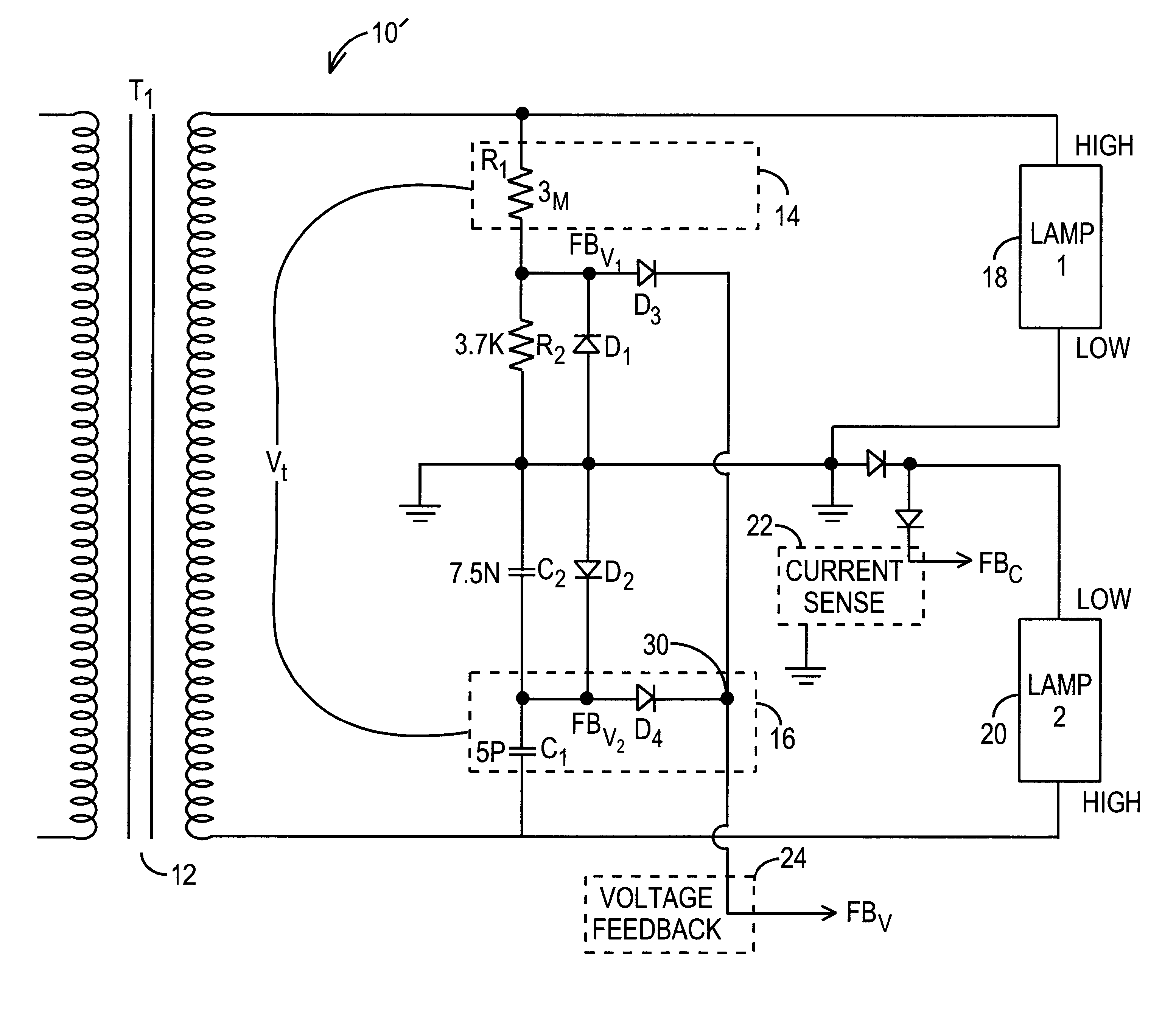
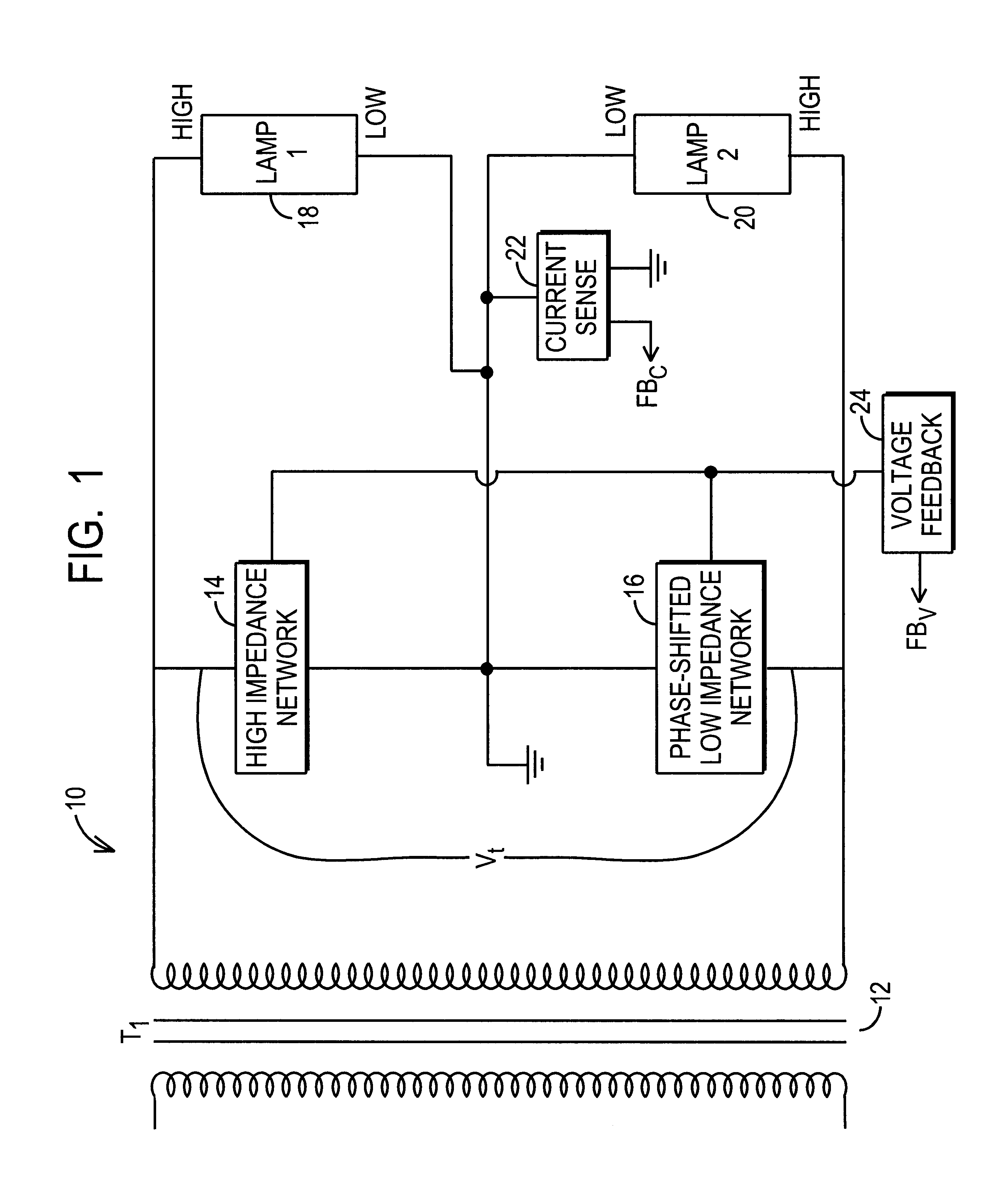
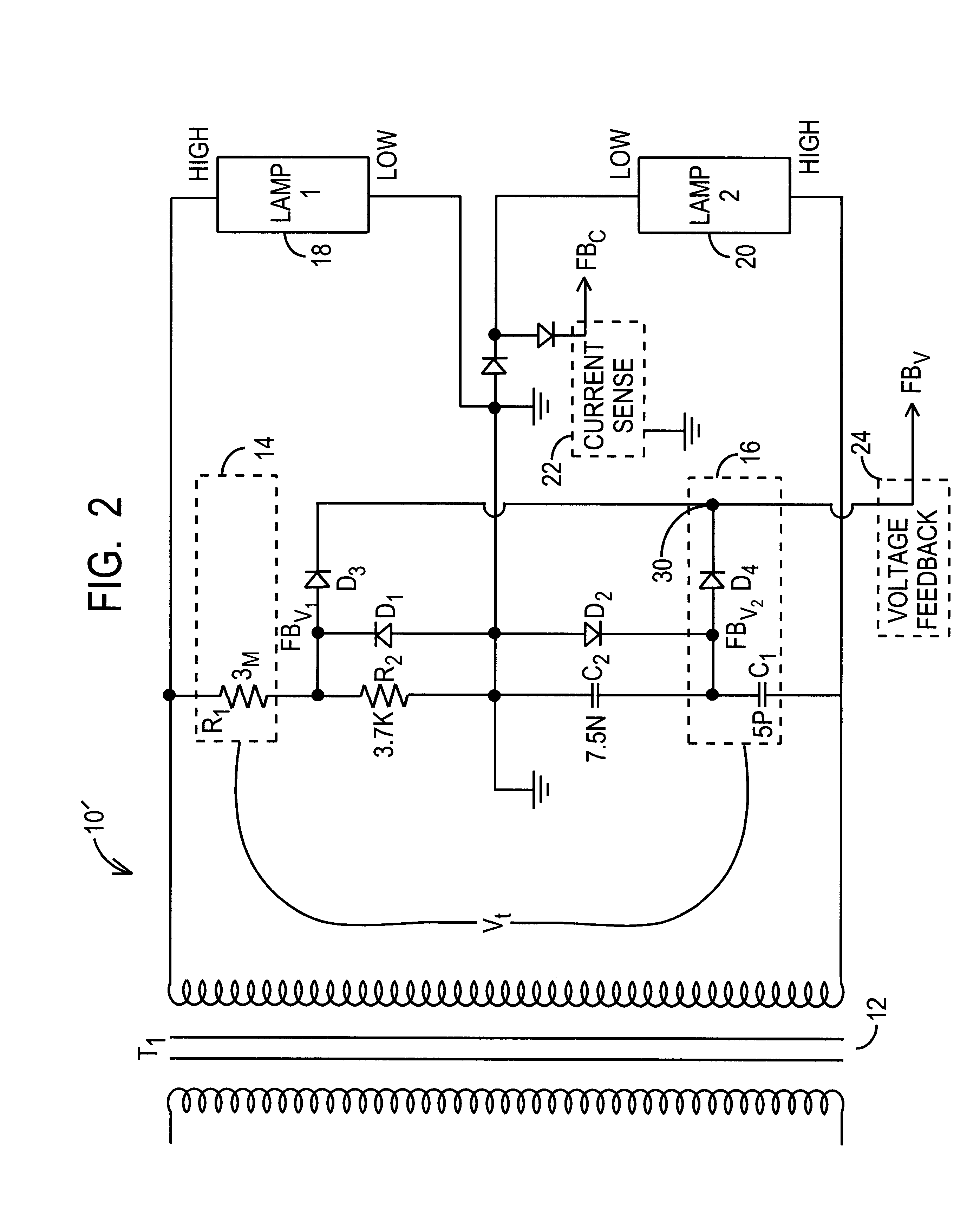
FIG. 1. is a block diagram of one exemplary load driving system 10 according to the present invention. More specifically, the system 10 is an exemplary lamp driving system. The loads in this exemplary embodiment comprise two lamps, Lamp1 and Lamp2, connected in series, however the present invention is to be broadly construed to cover any particular load. The transformer 12 delivers a stepped-up power source for the loads, Lamp1 and Lamp2. In the following description, the transformer will be generically referred as a power source, and should be broadly construed as such. Those skilled in the art will recognize that conventional inverter topologies may be used to drive the primary side of the transformer 12. Such inverter topologies include push-pull, Royer, half bridge, full bridge, etc., and all such inverters may be used with the lamp driving system 10 of the present invention. As an overview, the system 10 depicted herein permits two lamps to be connected in series without requir...


PUM


Abstract

A lamp driving system that includes a first impedance and a second impedance coupled to the secondary side of a transformer, where the second impedance has a phase shifted value compared to the first impedance. Two lamp loads are connected in series together, and in parallel to the first and second impedances and to the transformer. The phase shift between the impedances ensures that the transformer need not supply double the striking voltage to strike the series-connected lamps. A difference in the resistance between the first and second impedances ensures that the lamps ignite in a specified sequence.

Description

1. Field of the InventionThe present invention relates to a system and method for driving multiple loads. More particularly, the present invention relates to a system and method for driving two lamp loads connected in series.2. Description of Related ArtCCFLs (cold cathode fluorescent lamps) are widely employed in display panels. CCFLs require approximately 1500 Volts (RMS) to strike, and require approximately 800 Volts (RMS) for steady state operation. In displays where two CCFLs are required, a conventional technique is to couple the lamps in parallel with the secondary side of step-up transformer. In multiple lamp systems, the conventional technique for driving the lamps is to couple the lamps together in parallel with one another to the transformer. While this ensures voltage control during striking, this topology also requires impedance matching circuitry for the lamps. Also, current control in this topology is difficult since the current conditions of each lamp must be monitor...

Claims


Application Information

Patent Timeline
Patent Type & Authority Patents(United States)
IPC IPC(8): H05B41/20H05B41/232H05B41/24
CPCH05B41/232
Inventor CHOU, JOHNCRUZ, ARNEL DELA
Owner O2 MICRO INT LTD
Why Eureka
Try Eureka