
High reliability high voltage device housing system

a high-reliability, device-type technology, applied in the direction of x-ray tube gas filling, electric discharge tube, basic electric elements, etc., can solve the problems of oil leakage, oil contamination, drawbacks of oil-systems in practice,

Inactive Publication Date: 2003-05-13
KEVEX X RAV
View PDF4 Cites 30 Cited by
  • Summary
  • Abstract
  • Description
  • Claims
  • Application Information

AI Technical Summary

Benefits of technology

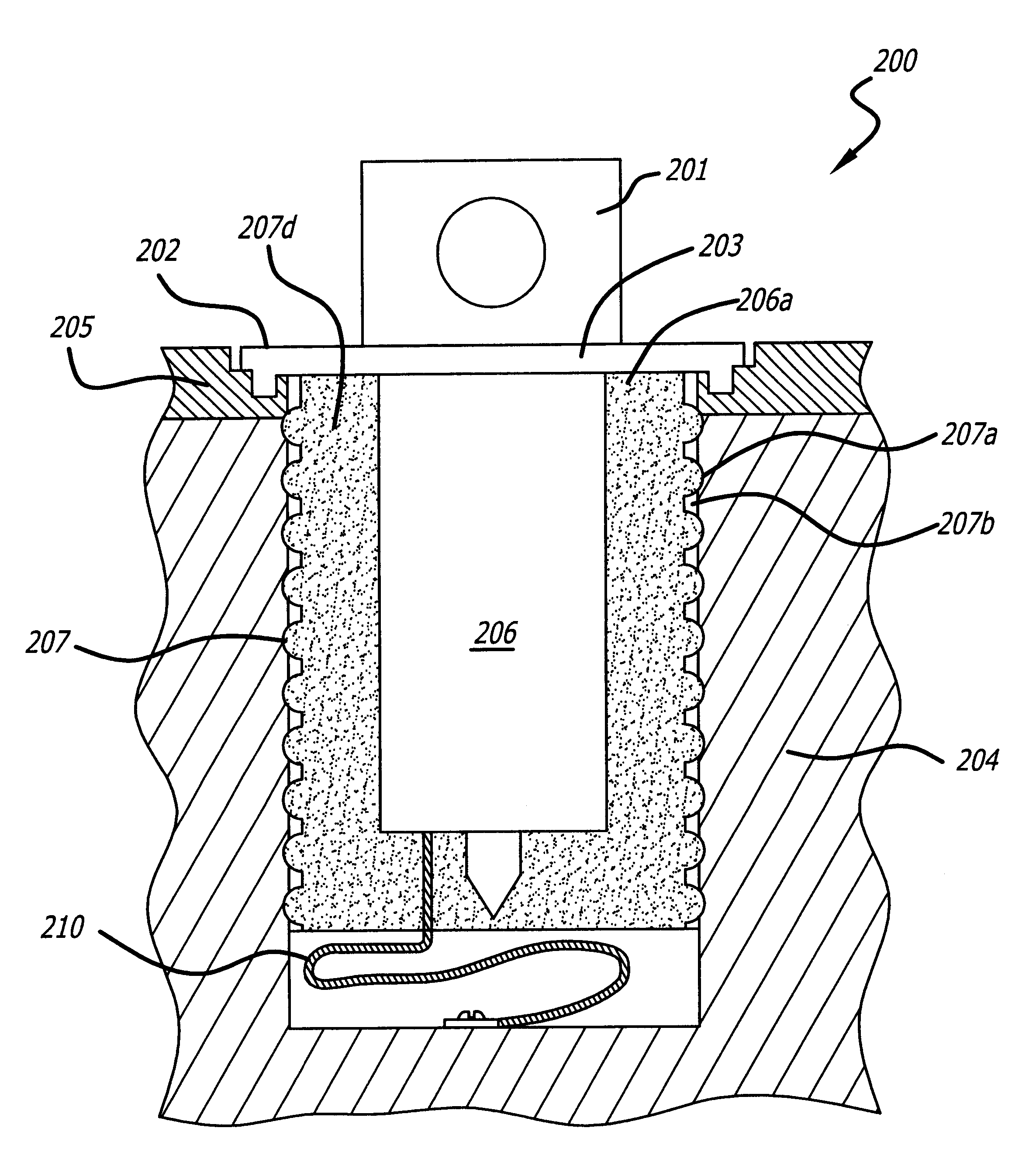
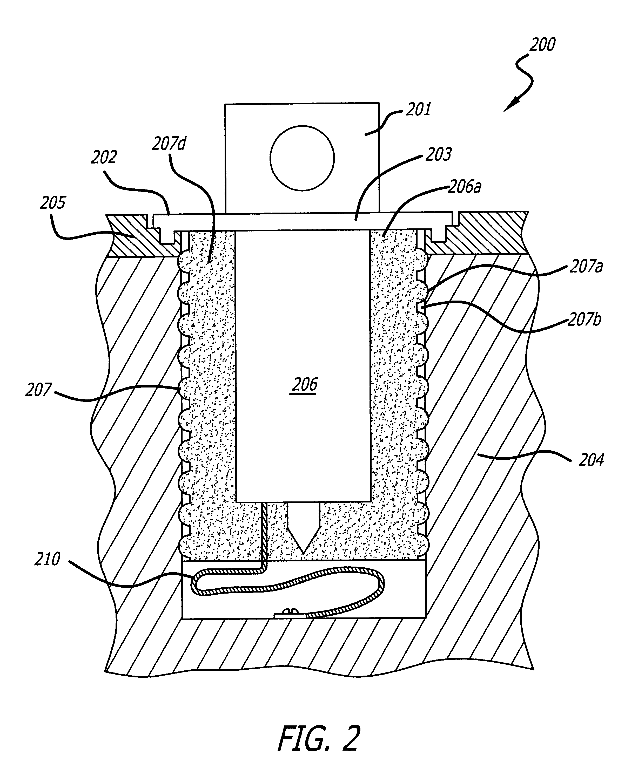
In one embodiment, a vacuum tube housing assembly of this invention includes a housing having an inner wall defining an enclosure into which a vacuum tube assembly is inserted. The vacuum tube assembly includes a vacuum tube having a outer side surface bearing an insulator, where the insulator includes a first portion generally continuously covering the outside surface of the vacuum tube and an integral second portion comprising a plurality of spaced apart projections or ribs extending around the outside surface and between the first portion and the inner wall of the housing. Air gaps are present between the respective projections or ribs, and the spacing of the ribs is established in a manner that inhibits high voltage breakdowns from occurring between the interface of the housing and the vacuum tube.
In one advantageous embodiment, the insulator used in the inventive vacuum tube housing assembly is formed from a curable silicon rubber molded in situ upon the exterior surface of the vacuum tube. The silicone rubber is molded and cured in place in a manner providing a series of spaced apart, raised circular ribs in the resulting rubber encapsulant formed upon the vacuum tube surface. This ribbed configuration of the rubber encapsulant formed upon the vacuum tube permits the resulting pre-potted vacuum tube to be properly positioned within the housing such that the spaced apart ribs physically engage the inner wall of the housing to form seal zones that alternate with intervening air gaps created between adjoining ribs and the inner wall of the housing. The resulting silicone rubber pre-potted vacuum tube assembly is endowed with high voltage insulation for high voltage connections within the housing. Moreover, the inventive pre-potted vacuum tube structure can be easily plugged into its housing and just as easily removed, if necessary, because the rubber encapsulant is not adhered to the housing, thereby greatly improving the manufacturability and serviceability of housed vacuum tubes. Furthermore, the rib features of the rubber encapsulant also serve to thermally couple heat from the vacuum tube to the housing.

Problems solved by technology

Additionally, such housing systems must often remove heat due to high temperatures generated by operation of the high voltage device.
However, drawbacks are associated with the oil systems in practice.
Oil also can leak from the housing over time.
Additionally, the oil can become contaminated, or degraded due to temperature and pressure fluctuations associated with the operation of the vacuum tube.
As a result, risk of failures from high voltage arcing, leakage and breakdown tend to increase over time for the liquid oil-based systems.
However, a drawback to using potting silicone resins in the above-stated conventional manner derives from the fact that a defective vacuum tube cannot be serviced or replaced without considerable difficulty since the cured potting material is adhesively bonded to not only the vacuum tube but also the housing, and thus it is not easily detached and removed from the housing.

Method used


Image

  • High reliability high voltage device housing system
  • High reliability high voltage device housing system
  • High reliability high voltage device housing system

Examples


Embodiment Construction

Illustrative embodiments and exemplary applications will now be described with reference to the accompanying drawings to disclose the advantageous teachings of the present invention.

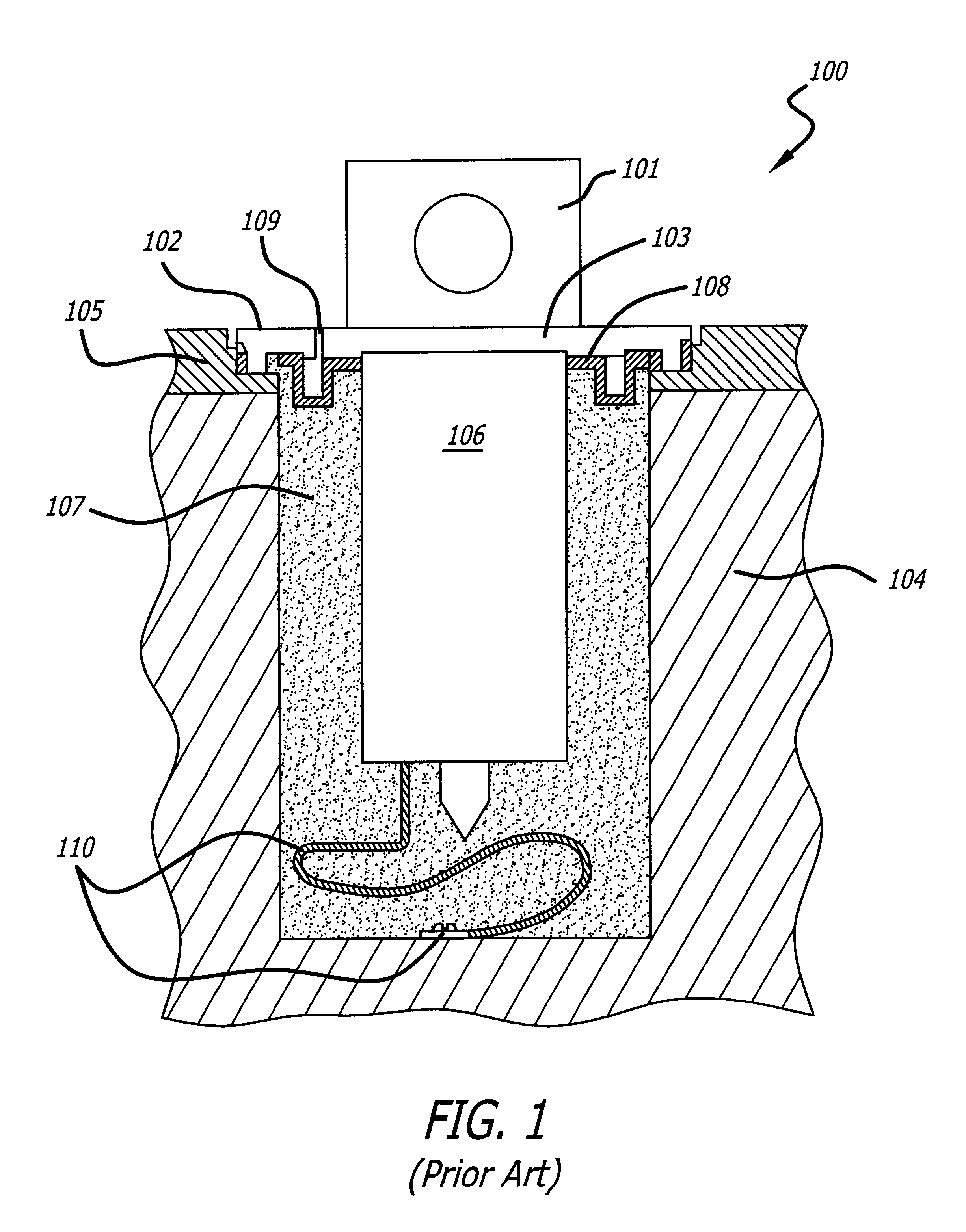
FIG. 1 illustrates a prior art packaged x-ray tube assembly 100 that employs an anode assembly 101 that is mounted with screws 102 through the mounting screw holes provided in the anode flange 103 to the epoxy housing 104 via the assembly mounting flange 105. This mounting is done so as to provide a leak-tight reservoir between the vacuum tube 106 and the housing 104 that retains Diala insulating oil 107. The seal means of the anode flange 103 to the assembly mounting flange 105 is a rubber oil expansion diaphragm 108 that seals in the oil 107 and also permits for oil expansion when the oil 107 becomes hot during operation of the packaged tube assembly 100. The expansion occurs by virtue of the vent hole 109 which allows air to escape which in turn permits the diaphragm 108 to collapse in response to the...


PUM


Abstract

A high voltage device housing assembly includes a housing and a high voltage assembly arranged in combination with an improved insulation system. The high voltage assembly is disposed within the enclosure defined by the housing, and the outer surface of the high voltage device, such as a vacuum tube, bears an insulator including a first portion generally continuously covering the side surface of the high voltage and an integral second portion comprising a plurality of spaced apart projections extending around the side surface and between the first portion and the inner wall of the housing. Air gaps are present between the respective projections, and the spacing of the ribs is established in a manner that inhibits ionic conduction from occurring between the housing and the high voltage device, which otherwise could lead to high voltage breakdowns.

Description

1. Field of the InventionThe present invention relates generally to the field of high voltage component housing systems, and more specifically to the encapsulation of high voltage vacuum devices within housings in an improved manner.2. Description of the Related ArtMany high voltage devices, such as vacuum tubes, high voltage resistors, and high voltage capacitors, that operate at high voltage in high voltage component systems require specialized housing methods to provide the necessary high voltage insulation of the high voltage devices, the interface to power supplies, and / or to mounting surfaces for subsequent use in systems. Additionally, such housing systems must often remove heat due to high temperatures generated by operation of the high voltage device. For instance, conventional x-ray tubes, such as those illustrated in U.S. Pat. Nos. 5,751,784 and 5,563,923, typically include a sealed glass or ceramic vacuum tube containing the x-ray generating means, which requires appropr...

Claims


Application Information

Patent Timeline
Patent Type & Authority Patents(United States)
IPC IPC(8): H05G1/00H05G1/04
CPCH05G1/04
Inventor ENCK, JR., RICHARD S.
Owner KEVEX X RAV
Learn More