Waveform signal compression and expansion along time axis having different sampling rates for different main-frequency bands

a wave signal and time axis technology, applied in the field of apparatus and method for compression and expansion of wave signals on time axis, can solve the problems of discontinuous connection points between segment waveform signals at the time of culling and repetition, noise generation, and inability to provide a fundamental solution to problems, etc., to achieve smooth compression, reduce the amount of wave signal processing of waveform signals, and increase the number of bands (frequency bands).

Inactive Publication Date: 2003-05-13
ROLAND CORP
View PDF29 Cites 30 Cited by
  • Summary
  • Abstract
  • Description
  • Claims
  • Application Information

AI Technical Summary

Benefits of technology

The present invention has been made in view of the problems of the conventional techniques described above. It is an object of the present invention to provide an apparatus and method for compression and expansion of a wave signal on a time axis that makes it possible to structure a low-cost system. This is achieved by dividing a waveform signal that is subject to compression and expansion on a time axis into mai

Problems solved by technology

However, when a continuous waveform is subject to the culling or repetition, connection points between segment waveform signals at the time of culling and repetition become discontinuous.
This results in another problem in that noises are generated.
However, this technique cannot completely prevent the fluctuation of the waveform signals or the generation of rippling, and therefore cannot provide a fundamental solution to the problems.
Ac

Method used


Image

  • Waveform signal compression and expansion along time axis having different sampling rates for different main-frequency bands
  • Waveform signal compression and expansion along time axis having different sampling rates for different main-frequency bands
  • Waveform signal compression and expansion along time axis having different sampling rates for different main-frequency bands

Examples


Embodiment Construction

Hereafter, the principle of an apparatus and method for compression and expansion of a wave signal on a time axis in accordance with the present invention will be described. The apparatus and method for compression and expansion of a wave signal on a time axis of the present invention uses the characteristic of the person's auditory sense that tends to react more to a logarithmic change than a linear change not only in the loudness but also on the frequency axis.

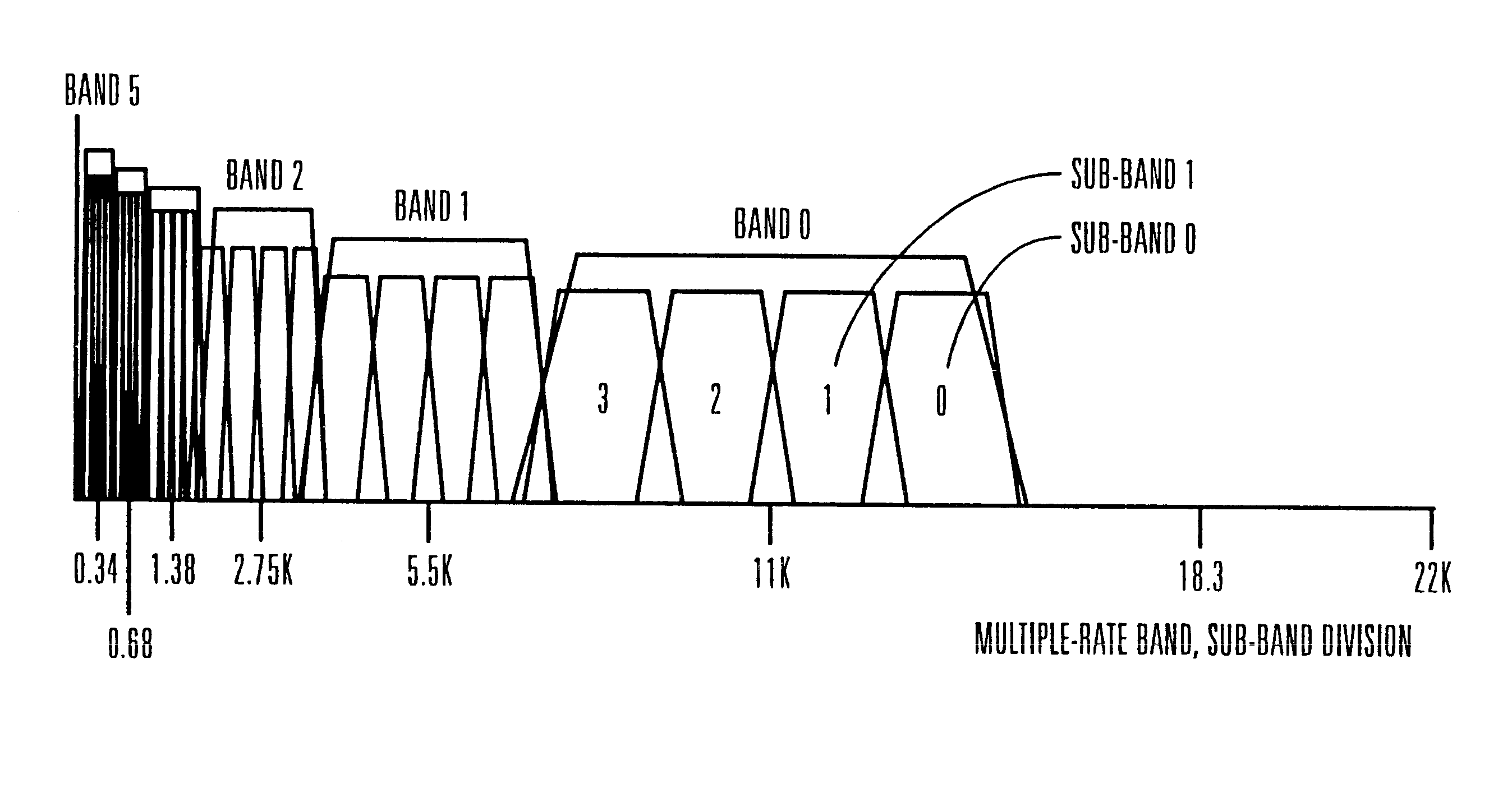
The multiple-rate sampling technique is a technique in which a frequency band of a waveform signal is divided into halves, and each one of the divided halves is further divided into smaller halves successively and, the sampling rate for each successively divided frequency band is accordingly reduced by half. As a result, the sampling rate lowers for a lower frequency band and, therefore, an overall-processing amount for processing the waveform-signal is reduced.

In the conventional multiple-rate sampling technique, each band ...


PUM


Abstract

An apparatus and method for compression and expansion of a wave signal on a time axis. A memory device stores waveform data representative of a waveform for each sub-frequency band of each main-frequency band of a wave signal, in which the wave signal is divided into a plurality of the main-frequency bands, each of the main-frequency bands is divided into a plurality of the sub-frequency bands. A plurality of time axis compression and expansion devices are provided for each of the sub-frequency bands for performing time axis compression and expansion of the waveform. A mixing device mixes signals provided from the time axis compression and expansion devices. Each of the time axis compression and expansion devices performs compression and expansion in a sampling rate that corresponds to one of the main-frequency bands that includes the sub-frequency band that is subject to the waveform time axis compression and expansion, wherein the sampling rate of at least one of the main-frequency bands is different from the sampling rate of at least one other of the main frequency bands.

Description

1. Field of the InventionThe present invention relates to an apparatus and method for compression and expansion of a wave signal on a time axis. More particularly, the present invention relates to an apparatus and method for compression and expansion of a wave signal on a time axis in which the compression and expansion of the waveform signal on a time axis can be performed smoothly.2. Description of Related ArtIn general, for example, the time axis compression and expansion technology (hereafter, referred to as "time stretch technology" as the circumstances warrant) has come to be utilized in the music production field as a technology for the reproduction of a waveform signal. In accordance with the time stretch technology, reproduction time of the waveform signal that has been recorded is compressed and expanded on the time axis.For example, the rotation speed of the tape on the tape recorder at the time of recording on the tape may be made different from the rotation speed of the...

Claims


Application Information

Patent Timeline
IPC IPC(8): G10L21/00G10L21/04G10H7/00G10L21/043
CPCG10L21/04
Inventor KIKUMOTO, TADAOHOSHIAI, ATSUSHIKUSAKABE, SATOSHI
Owner ROLAND CORP
Why Eureka
Try Eureka