Overhead cooling system with selectively positioned paths of airflow

a cooling system and airflow technology, applied in the field of cooling systems, can solve the problems of difficult to modify the cooling system accordingly, the cooling system is rigid, and the alteration of the cooling characteristics of existing cooling systems often proves a costly adventure, and achieves the effect of greater and greater efficiency

Inactive Publication Date: 2003-05-20
VERTIV CORP
View PDF11 Cites 72 Cited by
  • Summary
  • Abstract
  • Description
  • Claims
  • Application Information

AI Technical Summary

Benefits of technology

The growth of the computer industry and telephony over the past few decades has been phenomenal. The integration of these technologies has lead to grea

Problems solved by technology

One problem inherent with many existing cooling systems for electronic equipment is rigidity.
In the event the temperature characteristics within the temperature-cooled room changes, such as by the equipment being moved within the room or by additional equipment being added therein, it is very difficult to modify the cooling system accordingly.
Consequently, altering the cooling characteristics of existing cooling systems frequently proves a costly adventure.
Floor-based cooling systems present additional difficulties other than rigidity in its cooling characteristics.
Such systems require the equipment cabling to be plenum rated, thereby increasing system cost.
Floor-based cooling systems also possess the tendency to distribute noise and vibrations, w

Method used


Image

  • Overhead cooling system with selectively positioned paths of airflow
  • Overhead cooling system with selectively positioned paths of airflow
  • Overhead cooling system with selectively positioned paths of airflow

Examples


Embodiment Construction

The present invention will now be described more fully hereinafter with reference to the accompanying drawings in which a preferred embodiment of the invention is shown. This invention may, however, be embodied in many different forms and should not be construed as being limited to the embodiment set forth herein. Rather, the embodiment is provided so that this disclosure will be thorough and complete, and will fully convey the invention to those skilled in the art.

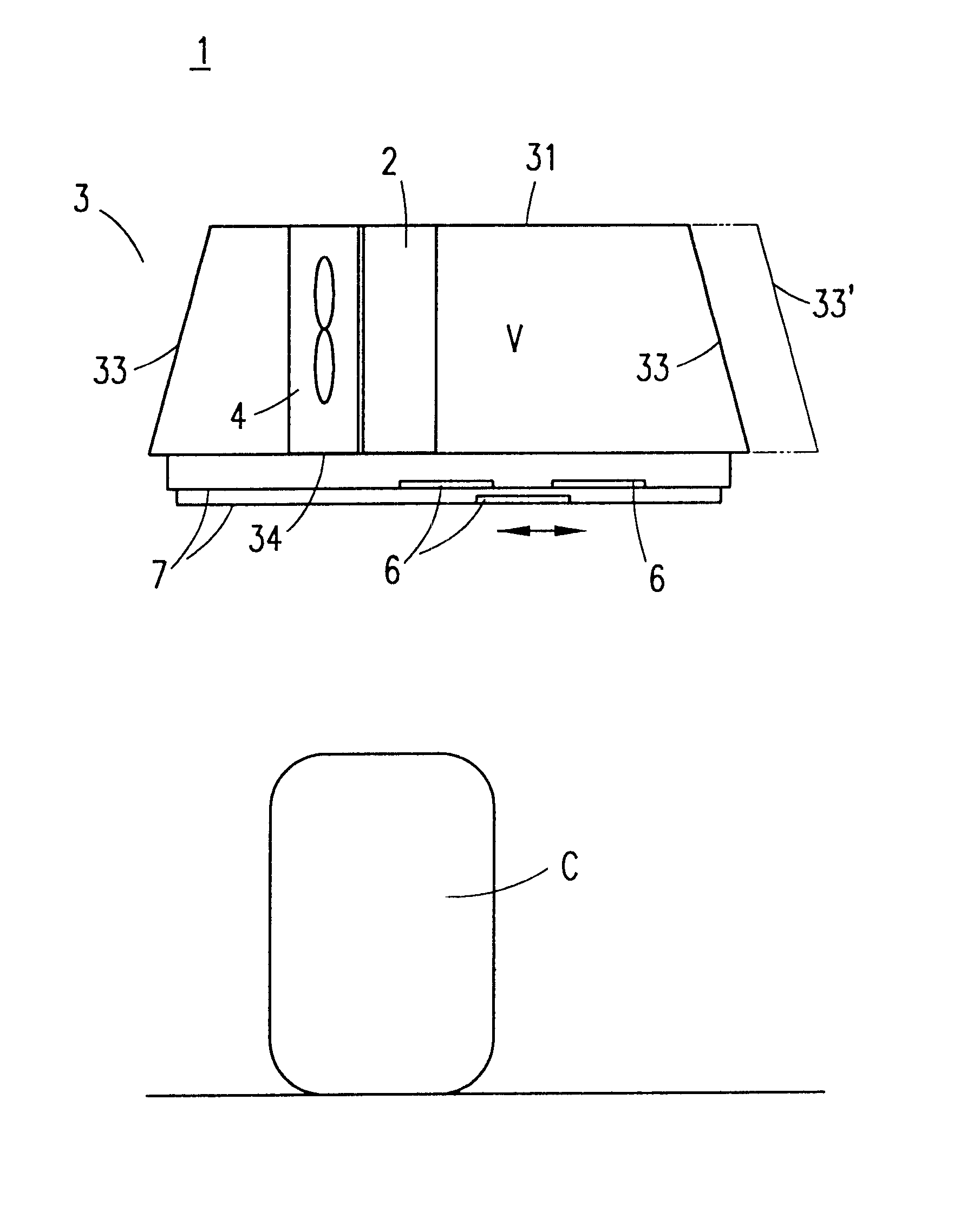
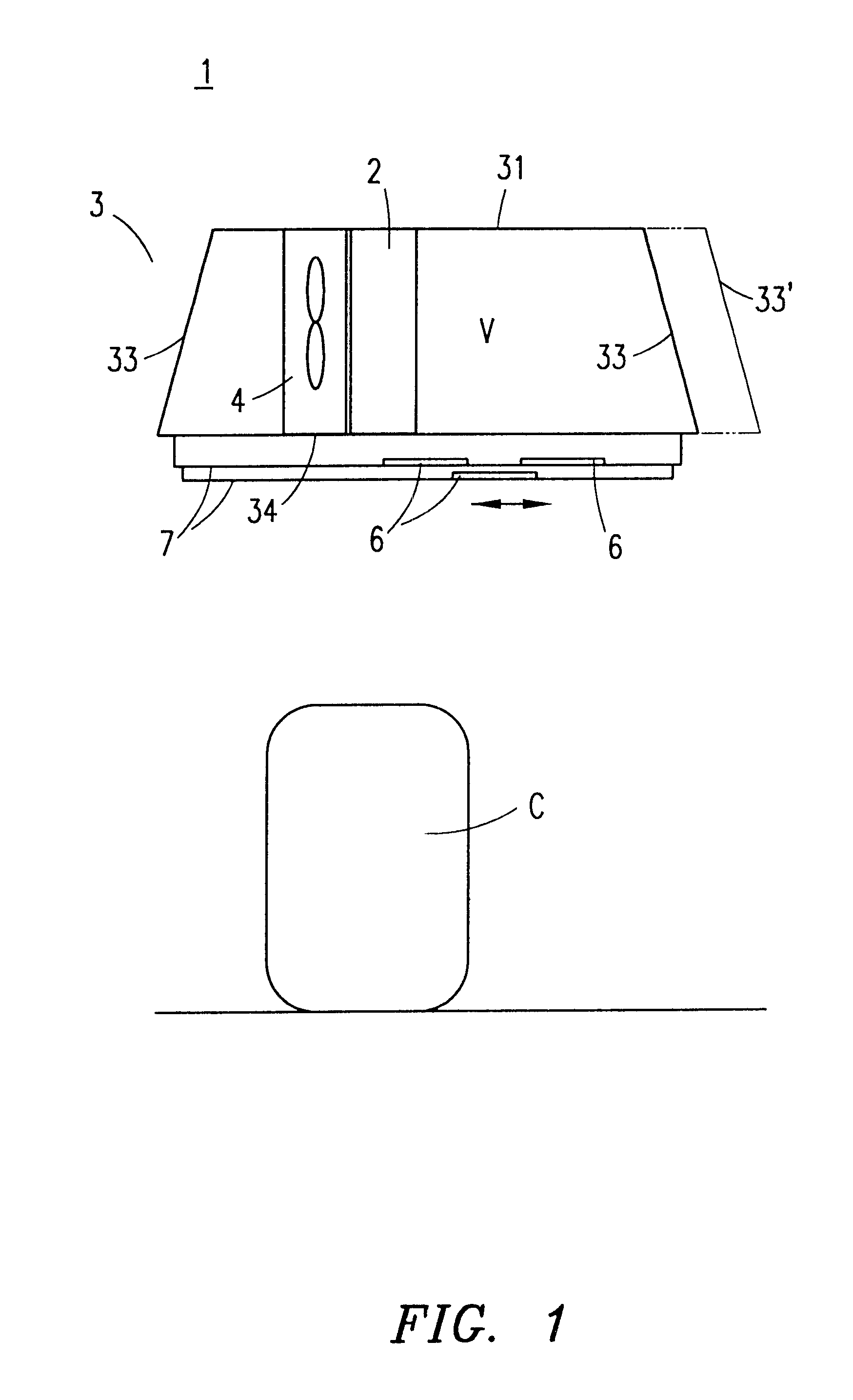
Referring to FIGS. 1-6, there is shown a cooling, system 1 according to an embodiment of the present invention. Cooling system 1 is adapted to provide cooled air to one or more heat generating object(s) C, such as a computer equipment. As shown in FIG. 1, cooling system 1 may be disposed above the heat generating object(s) C that cooling system 1 is intended to cool. As such, cooling system 1 may be attached along or suspended from a ceiling of the room in which the heat generating object C is located. Cooling system 1 in...


PUM


Abstract

A method and system are disclosed for cooling a heat generating object. A coolant is passed through a heat exchanger so that heated air passing through the heat exchanger is cooled. A fan unit is selectively positioned adjacent to a first side of the heat exchanger. When activated, the fan unit draws the cooled air through the heat exchanger and directs the cooled air towards the heat generating object. The fan unit may be repositioned along a second side of the heat exchanger so as to redefine the flow of air drawn from and directed towards the heat generating object.

Description

1. Technical Field of the InventionThe present invention relates to cooling systems for cooling electronic equipment, and particularly to systems for cooling electronic equipment that are reconfigurable to allow customized air flow in proximity to the electronic equipment.2. Background and Objects of the InventionThe growth of the computer industry and telephony over the past few decades has been phenomenal. The integration of these technologies has lead to greater and greater efficiencies as larger numbers of communications are handled by fewer components, which are typically housed in a central control room.One problem inherent with many existing cooling systems for electronic equipment is rigidity. Many existing cooling systems are built into and / or under the flooring of a temperature-controlled room having equipment needing to be cooled. Such cooling systems oftentimes employ fixed conduits or other piping for directing cooled air along a subsurface of the flooring and upwardly ...

Claims


Application Information

Patent Timeline
IPC IPC(8): H05K7/20
CPCH05K7/206
Inventor STAHL, LENNARTBELADY, CHRISTIAN
Owner VERTIV CORP
Why Eureka
Try Eureka