
Hydrodynamic coupling device

a technology of coupling device and hydraulic coupling, which is applied in the direction of coupling, fluid gearing, assembly machine, etc., can solve the problems of coupling device and drive unit, difficult to connect the subassembly of the coupling device and transmission to the drive unit, and the inability of the two driver arrangements to disengage from one another axially

Inactive Publication Date: 2003-05-20
MANNESMANN SACHS AG
View PDF5 Cites 19 Cited by
  • Summary
  • Abstract
  • Description
  • Claims
  • Application Information

AI Technical Summary

Benefits of technology

In this way, an at least partial decoupling of the hydrodynamic coupling device from the transmission by way of subassembly can be achieved, to facilitate the assembly of a whole system.
The stator wheel support can be part of the coupling device. Integration of the work fluid pump arrangement in the area of the stator wheel support is achieved by a subassembly. This results in two particularly advantageous effects. First, the work fluid pump arrangement subassembly is fully integrated in the coupling device itself, so that the coupling device itself can form a functional unit. Second, support of this work fluid pump arrangement with respect to torque is carried out by means of the same supporting arrangement which also provides support of the stator wheel. This leads to an appreciably simplified design.
It is advantageous for a fluid channel arrangement to be provided in the second supporting element, wherein the work fluid can flow toward and away from the pump space through this fluid channel arrangement.

Problems solved by technology

Joining the subassembly of the coupling device and transmission to the drive unit is a relatively difficult undertaking because the installation space available between the hydrodynamic coupling device and the drive unit is very limited.
It is therefore impossible for these two driver arrangements to disengage from one another axially.

Method used


Image

  • Hydrodynamic coupling device
  • Hydrodynamic coupling device
  • Hydrodynamic coupling device

Examples


Embodiment Construction

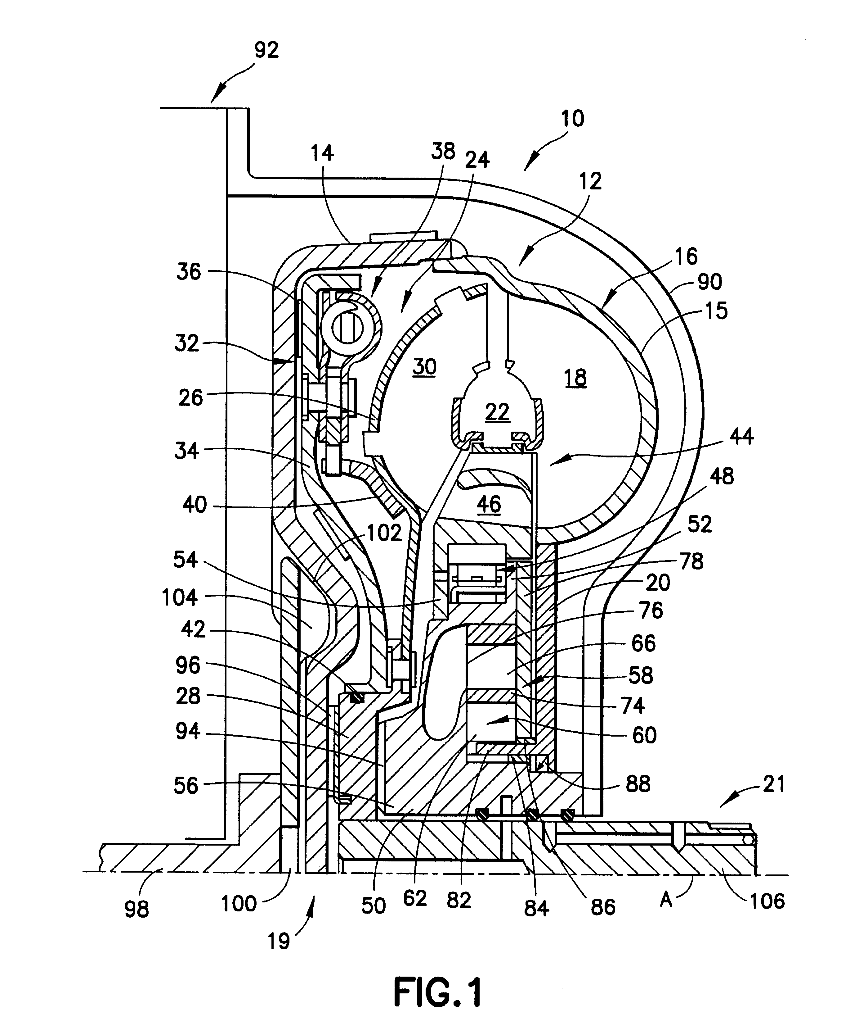
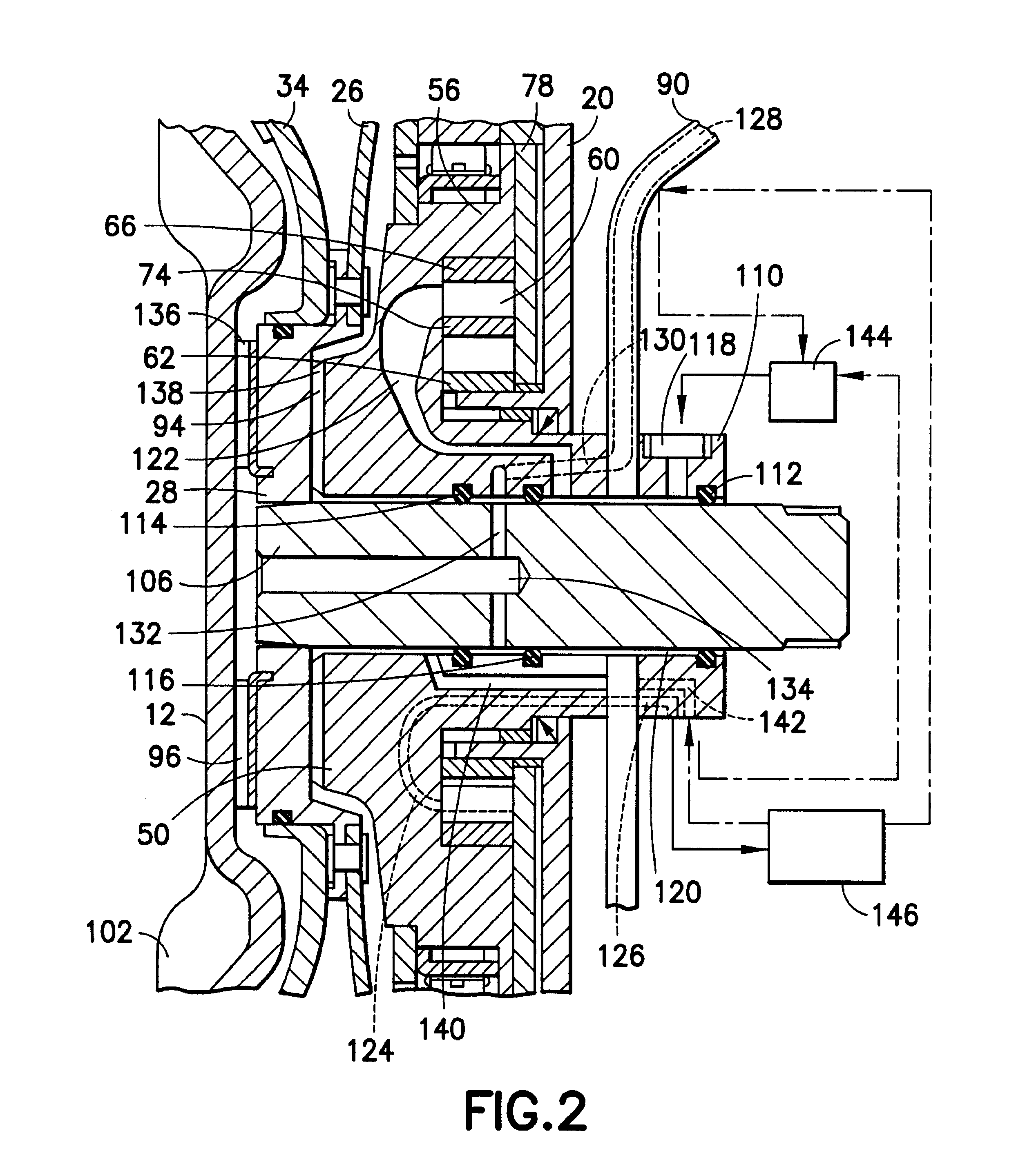
A first construction type of a hydrodynamic coupling device according to the invention is described with reference to FIGS. 1 to 3.

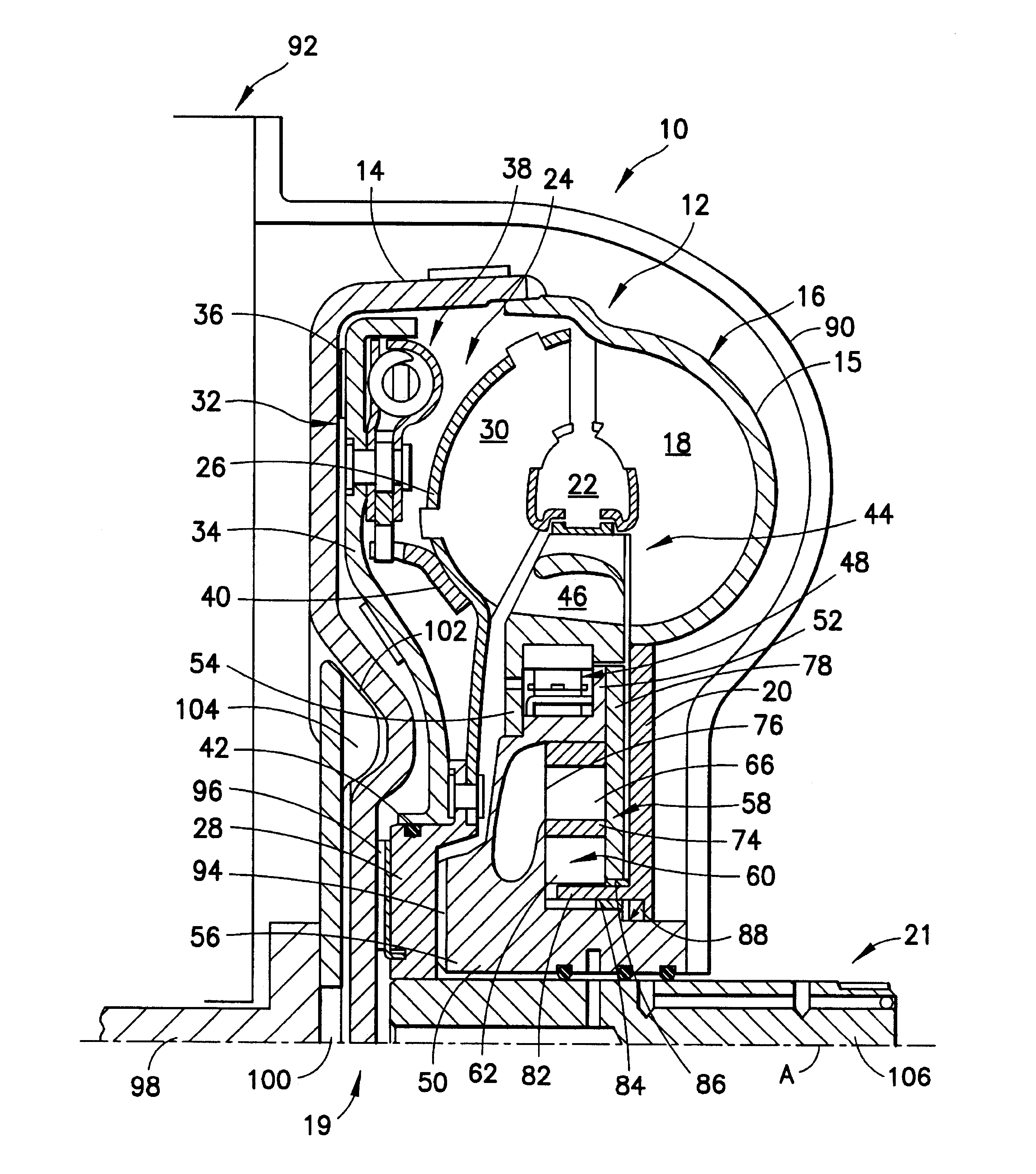
The hydrodynamic coupling device 10 is constructed as a torque converter in the present case. This torque converter 10 has, in a manner known per se, a converter housing 12 which comprises a housing cover 14 and an impeller wheel shell 15 of an impeller wheel 16, this impeller wheel shell 15 being fixedly connected with the housing cover 14 on the radial outside, e.g., by welding. In its radial outer area, the impeller wheel shell 15 carries a plurality of impeller wheel vanes 18 which are arranged successively in the circumferential direction and is connected on the radial inner side with an impeller wheel hub 20. A turbine wheel 24 which, in turn, has a turbine wheel shell 26 and a turbine wheel hub 28 fixedly connected with the latter is arranged in the interior 22 of the torque converter 12. The turbine wheel shell 26 carries turbine wheel vanes 30 w...


PUM

PropertyMeasurementUnit
torqueaaaaaaaaaa
transmitting torqueaaaaaaaaaa
braking/driving torqueaaaaaaaaaa

Abstract

A hydrodynamic coupling device for producing a torque transmission connection between a drive unit and a transmission is provided including a first coupling device attached to the drive unit for coupling the hydrodynamic coupling device with the drive unit for transmitting a torque between the hydrodynamic coupling device and the drive unit and a second coupling device attached to the transmission for coupling the hydrodynamic coupling device with the transmission for transmitting a driving and / or braking torque between the hydrodynamic coupling device and the transmission. A method of making a hydrodynamic coupling device is also provided.

Description

1. Field of the InventionThe present invention relates to a hydrodynamic coupling device for forming a torque transmission connection between a drive unit and a transmission, the coupling device having a first coupling area in which the hydrodynamic coupling device is couplable or coupled to the drive unit in a torque-transmitting manner and a second coupling area in which the hydrodynamic coupling device is couplable or is coupled to the transmission in a torque-transmitting manner. The present invention also relates to a method of making a hydrodynamic coupling device.2. Description of the Related ArtHydrodynamic coupling devices used in drivetrains in motor vehicles for hydrodynamic torque converters are principally constructed to be relatively extensively integrated in the transmission with respect to function and mechanical subassemblies. Usually, when constructing drivetrains, a hydrodynamic coupling device of this type is usually first combined with the transmission to form a...

Claims


Application Information

Patent Timeline
Patent Type & Authority Patents(United States)
IPC IPC(8): F16H45/00F16H45/02
CPCF16H45/02F16H2045/007Y10T29/49904F16H2045/0294F16H2045/0268
Inventor GLOCK, WILFRIEDHINKEL, RUDIGERSASSE, CHRISTOPH
Owner MANNESMANN SACHS AG
Learn More