Shielding method and apparatus using transverse slots

a shielding method and transverse slot technology, applied in the field of well logging, can solve the problems of significant undesired em field components, no disclosure of shielding implementation, and no disclosure of shielding concept and physical setup in communications applications different from that involved in logging applications

Inactive Publication Date: 2003-05-20
SCHLUMBERGER TECH CORP
View PDF18 Cites 148 Cited by
  • Summary
  • Abstract
  • Description
  • Claims
  • Application Information

AI Technical Summary

Problems solved by technology

However, under actual operating conditions, there are various factors that give rise to the generation of significant undesired EM field components.
None of these disclosures address the implementation of shields as alternative means to achieve selective EM energy attenuation.
However, the concept and physical setup in communications applications is different from that involved with logging applications.

Method used


Image

  • Shielding method and apparatus using transverse slots
  • Shielding method and apparatus using transverse slots
  • Shielding method and apparatus using transverse slots

Examples


Embodiment Construction

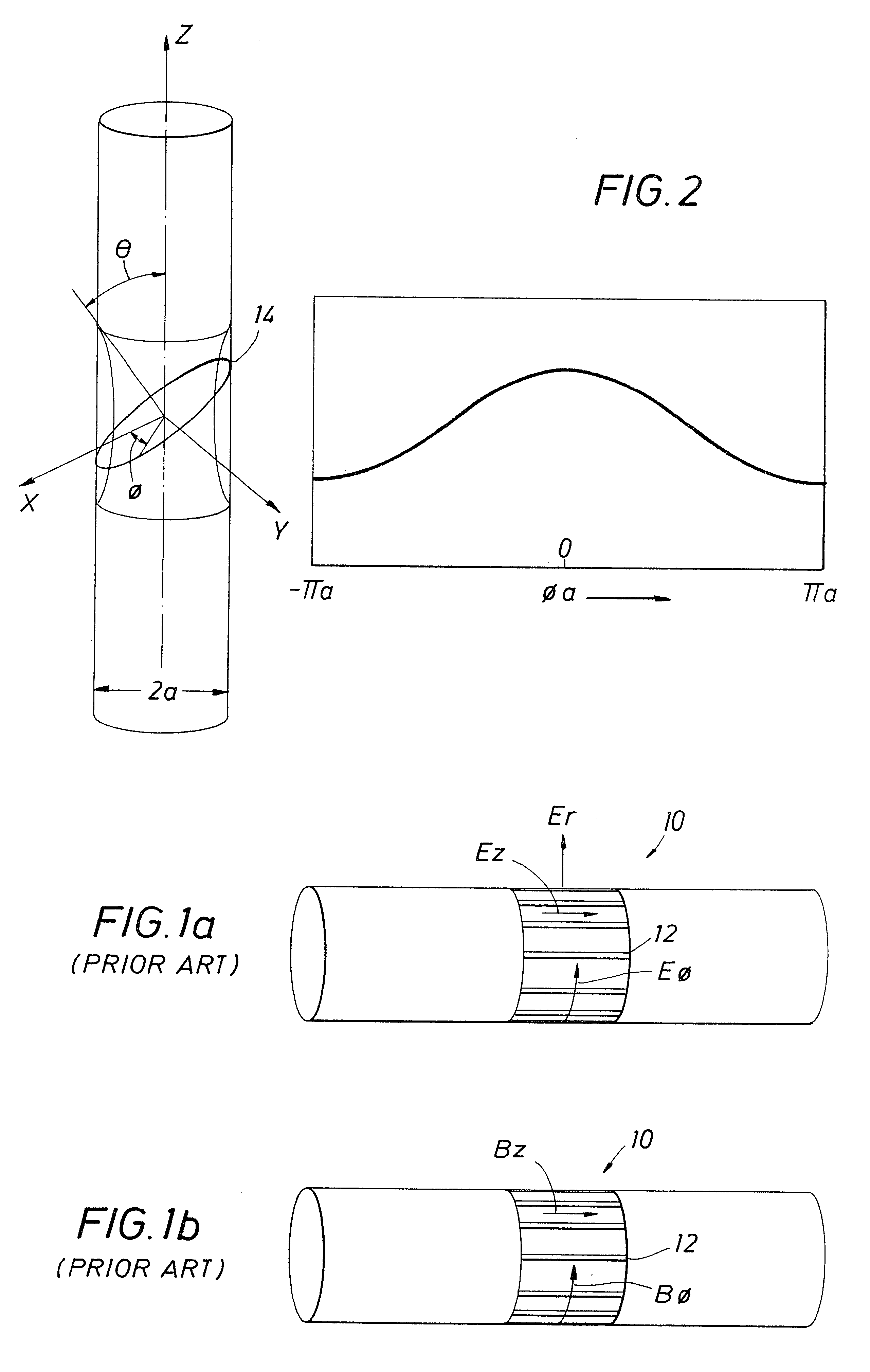
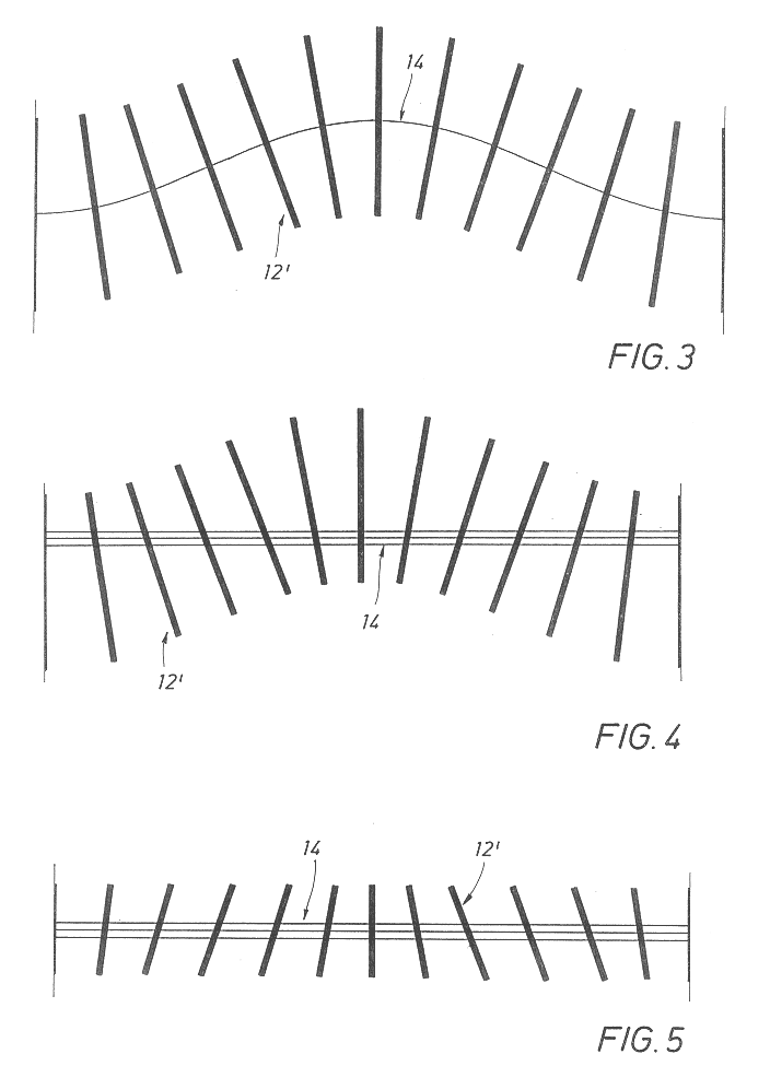
As discussed above, conventional shields used in logging instruments universally have slots that are aligned along the longitudinal axis of the instrument. The orientation of the slots is perpendicular to the electric field generated by the source within or the field that is to be detected by the sensor. If the incident field has an unwanted component of the electric field that lies along the slot, then currents will flow in the metal to cancel that field and only the normal component will remain. For conventional induction or propagation instruments, the desired electric field is azimuthal, and longitudinal slots allow that field to pass. If the coil was wound at an angle .theta. to the axis of the instrument, then the desired electric field is no longer azimuthal, but rather has both azimuthal and longitudinal components that vary as a function of the azimuthal position.

FIG. 2 illustrates a coil 14 wound at an angle .theta. to the longitudinal axis (represented by dashed lines) of...


PUM


Abstract

A shielding method and apparatus for an antenna disposed on an elongated support adapted for disposal within a borehole. The shield providing predetermined attenuation of one or more electromagnetic energy field components as the field components interact with the shield. The shield composed of a flexible strip or cylindrical body and respectively comprising a transverse conductive element or a transverse slot therein. The shields being adapted to cover an antenna mounted on the support. The shields being compatible for use in conjunction with saddle, tilted coils or multi-layered tri-axial coils to produce a pure transverse magnetic dipole electromagnetic field. The shields are also used in methods for shielding an antenna disposed on a support to provide predetermined attenuation of an electromagnetic field component as the field components interact with the shield.

Description

1. BACKGROUND OF THE INVENTION1.1. Field of the InventionThis invention relates to the field of well logging, and more particularly, to improved shields for use with logging instruments using sources or sensors having a transverse or tilted magnetic dipole.2.2. Description of Related ArtElectromagnetic (EM) logging instruments have been employed in the field of hydrocarbon exploration and production for many years. These logging instruments or "sondes" entail an elongated support member equipped with antennas that are operable as sources and / or sensors. These antennas are generally coils of the cylindrical solenoid type and are comprised of one or more turns of insulated conductor wire that is wound around the support. U.S. Pat. No. 4,873,488 (assigned to the present assignee), for example, describes logging instruments equipped with antennas disposed along a central support.In operation, a transmitter antenna is energized by an alternating current to emit EM energy into the formati...

Claims


Application Information

Patent Timeline
Patent Type & Authority Patents(United States)
IPC IPC(8): G01V3/28G01V3/18G01V3/08G01V3/30H01Q7/00H01Q17/00
CPCG01V3/28H01Q17/001H01Q7/00G01V3/30H01Q1/526H01Q13/10G01V3/08
Inventor OMERAGIC, DZEVATSEYDOUX, JEANROSTHAL, RICHARD A.
Owner SCHLUMBERGER TECH CORP
Why Eureka
Try Eureka