Optical cables with flexible strength sections

a technology of optical cables and flexible sections, applied in the direction of cables, insulated conductors, instruments, etc., can solve the problems of relatively large, relatively stiff cables, and high cost of cables

Inactive Publication Date: 2003-05-20
CORNING CABLE SYST LLC
View PDF8 Cites 92 Cited by
  • Summary
  • Abstract
  • Description
  • Claims
  • Application Information

AI Technical Summary

Benefits of technology

One aspect of the present invention includes a fiber optic cable having at least one optical component therein, a cable jacket surrounding the optical component, and strength sectio

Problems solved by technology

The background art includes cables that can be exp

Method used


Image

  • Optical cables with flexible strength sections
  • Optical cables with flexible strength sections
  • Optical cables with flexible strength sections

Examples


first embodiment

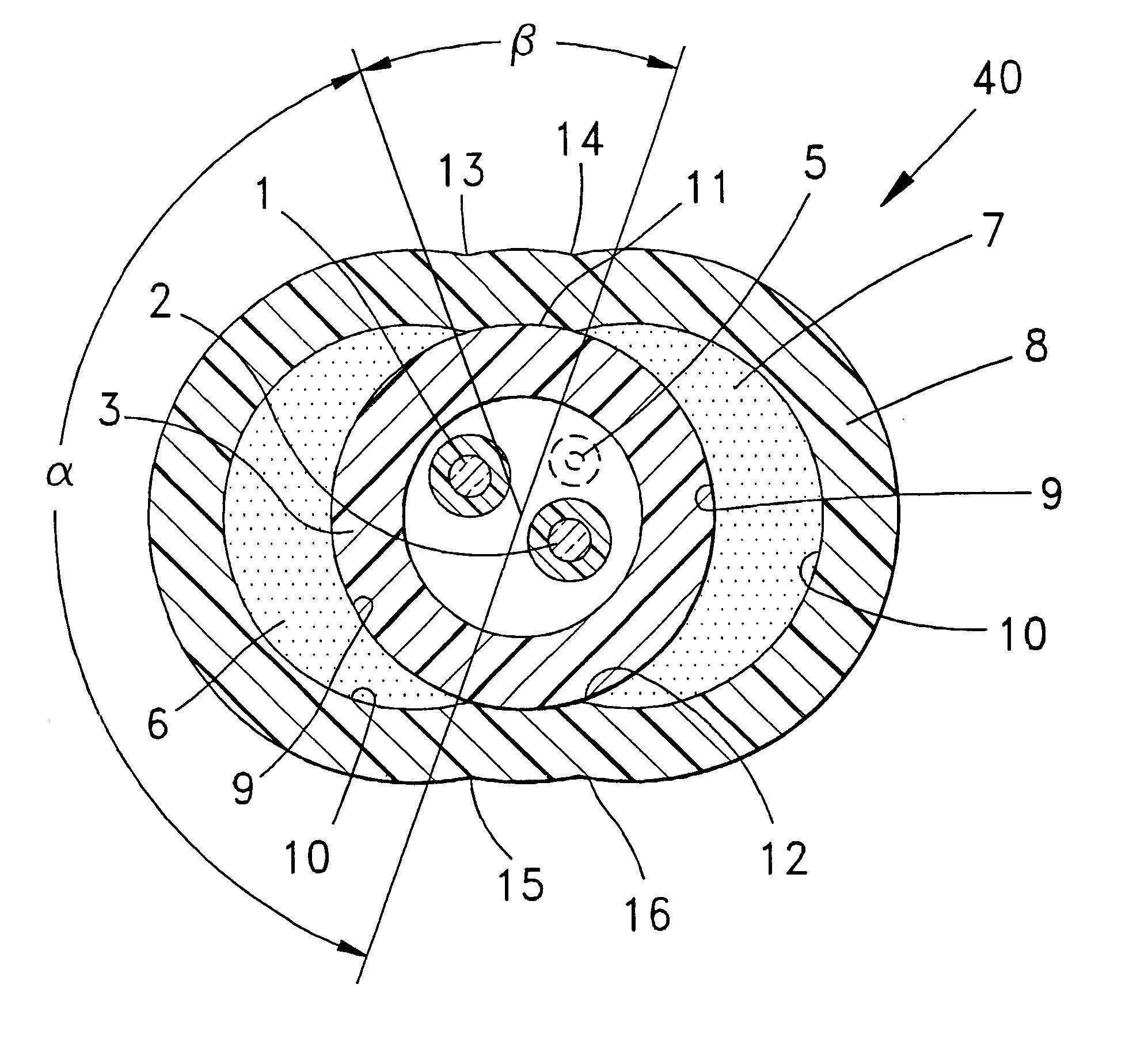
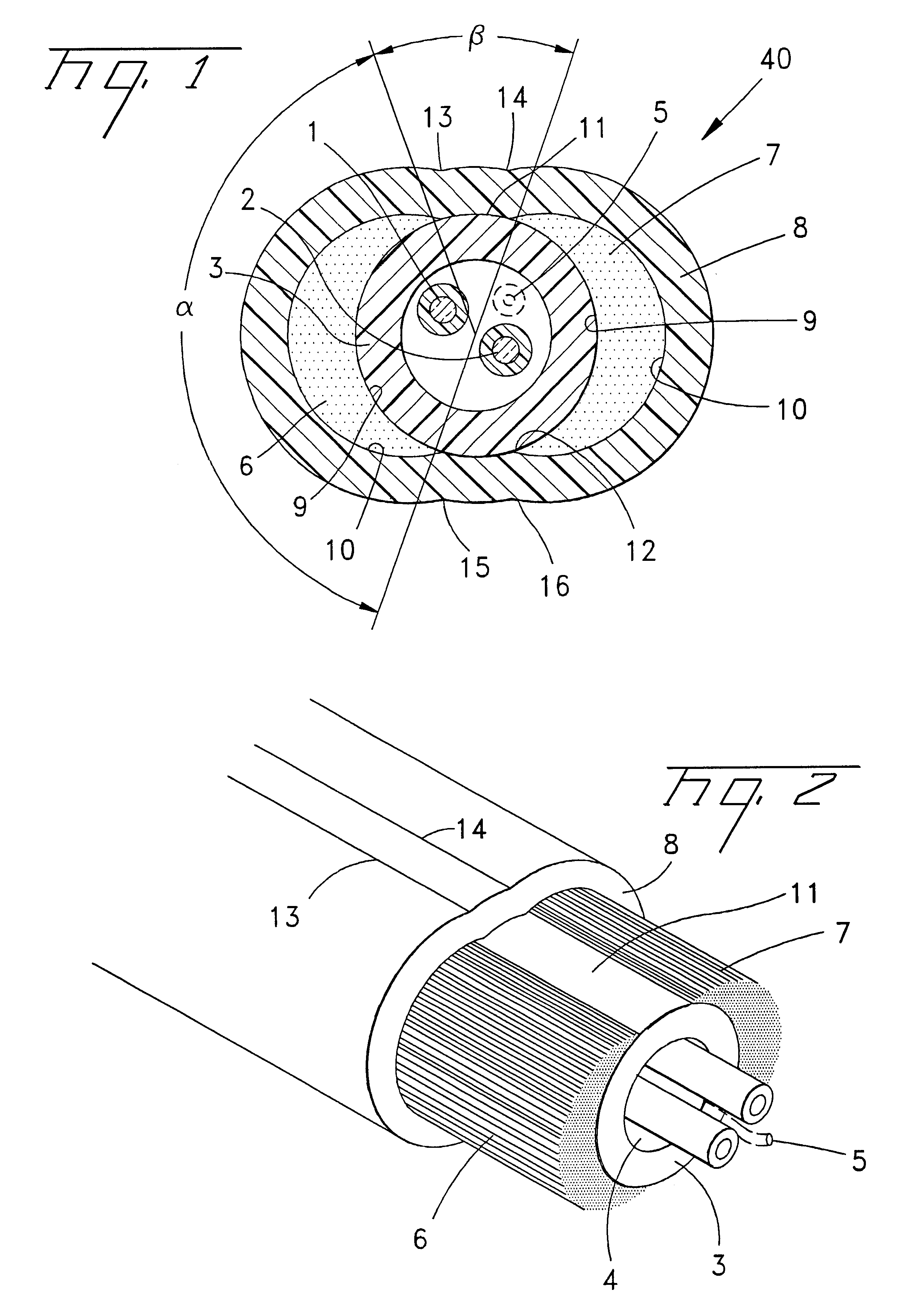
FIGS. 1 and 2 show a fiber optic cable 40 according to the present invention. In a preferred embodiment, fiber optic cable 40 includes an optical component that, for example, includes at least one, but more preferably at least two, silica-based optical fibers loosely received in a buffer tube 3 or tight buffered fibers (not shown). Tube 3 is preferably formed of a theromoplastic material, for example, impact-modified polypropylene or an aromatic polyamide, and is preferably aligned with a generally centrally disposed longitudinal axis of the cable. The preferred ID of tube 3 is about 1.0 mm, and the preferred OD is about 1.8 mm to about 3.0 mm. Preferably there is a controlled excess fiber length compared with the length of the tube to protect the fibers from risk elongation or fracture. Tube 3 preferably includes a water-blocking substance, e.g., a grease or a superabsorbent compound. Super absorbent materials are commercially available in yarn, tape or powder form, and for the pre...

second embodiment

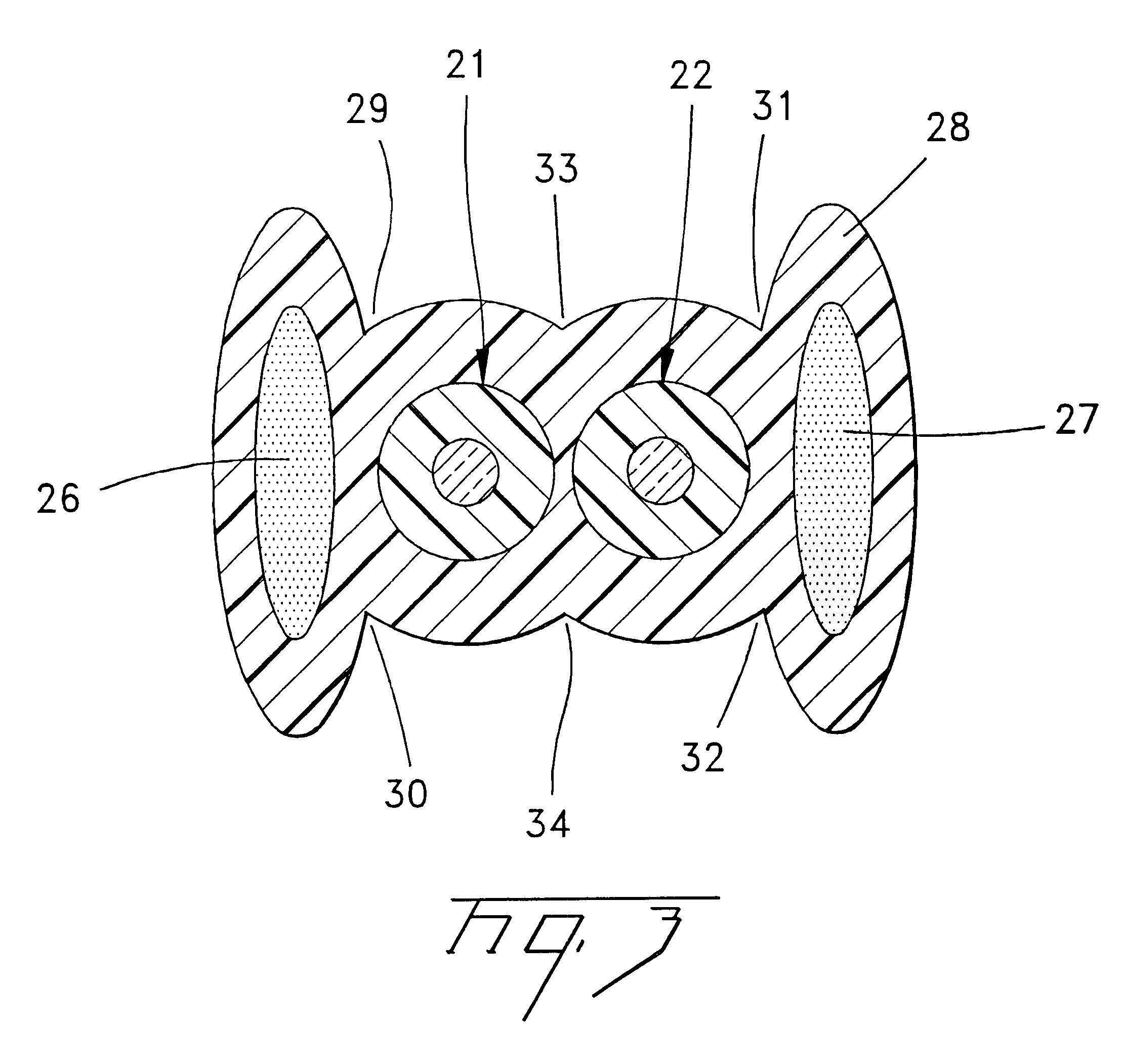
FIG. 3 shows the invention, using tight buffered fibers 21 and 22, for example, about 900 .mu.m OD, with sufficient resistance to tensile forces to be used without a loose enclosing tube. The buffered fibers are directly embedded in jacket 28 that also embeds generally oval strength sections 26 and 27. The strength sections include, for example, aramid fibers or fiberglass. Metallic substances may be used as well, e.g., steel or copper wires or fibers. A transverse dimension of at least one but preferably both of the strength sections is greater than an OD of an optical component 21,22. The transverse dimension is a larger than the optical component by a factor of about 1.10 to about 30, preferably about 1.5 to 20, and most preferably about 2.0 to 10 times the OD of the optical component. The relatively large transverse dimension absorbs clamping forces, and is useful in avoiding the application of direct cable clamping forces to the optical components. Other materials and cross sec...


PUM


Abstract

A fiber optic cable (40) having at least one optical component (1,2,3) therein, and a cable jacket (8) surrounding the optical component. Strength sections (6,7) are defined between the optical-component and the cable jacket, the strength sections comprising generally crescent-like cross sections. The generally crescent-like cross sections have respective generally concave and generally convex faces (9,10). The generally concave face (9) has a general center that is preferably aligned with the longitudinal axis of the cable, and the generally convex face (10) has a general center that is preferably offset from a longitudinal.axis of the fiber optic cable. The convex faces subtend respective angles (prop) of about 45° to about 160°. The cable jacket (8) defining contact interfaces (11,12) with the optical component, the contact interfaces being respectively disposed between the strength sections (6,7). A fiber optic cable having relatively large, force-absorbing transverse dimensions is also disclosed.

Description

The present invention relates to fiber optic cables generally, and, more particularly, to fiber optic cables having strength sections.The background art includes cables that can be expensive, relatively stiff, and / or relatively large. For example, U.S. Pat. No. 5,651,081 discloses a composite cable with optical fibers housed in a loose tube that is contained within a plastic jacket. The jacket embeds insulated electrical conductors and optionally also metallic strength members and ripcords. The cable core loosely contains at least one optical fiber, one or more electrical conductors having an outer polymer insulating layer, one or more strength members, and a surrounding protective jacket. The protective jacket is formed of a polymer material that forms a distinct mechanically separate phase from the polymer material forming the insulation layer surrounding the respective electrical conductors. For example, the jacket can be made of a polymer material having a melting temperature lo...

Claims


Application Information

Patent Timeline
IPC IPC(8): G02B6/44H01B7/18
CPCH01B7/183H01B7/182G02B6/4429G02B6/4416
Inventor GIMBLET, MICHAEL J.DUNN, JR., KENNETH F.
Owner CORNING CABLE SYST LLC
Why Eureka
Try Eureka