Method and apparatus for monitoring consumable performance

a consumable performance and monitoring method technology, applied in the direction of total factory control, programme control, electric programme control, etc., can solve the problems of increasing the time required to process the wafers in the tool, affecting the performance of the tool in which it is employed, and the polishing pad and the carrier head are subject to gradual deterioration

Inactive Publication Date: 2003-05-20
GLOBALFOUNDRIES US INC
View PDF11 Cites 78 Cited by
  • Summary
  • Abstract
  • Description
  • Claims
  • Application Information

AI Technical Summary

Problems solved by technology

This depletion affects the performance of the tool in which they are employed.
Generally, these adjustments increase the time required to process the wafers in the tool.
Both the polishing pad and the carrier heads are subject to gradual deterioration.
This degradation gradually decreases the polishing rate of the CMP tool over the life of the pad and carriers.
Eventually, a polishing pad may fail catastrophically and cease to polish entirely.
Certain sputtering targets, such as gold, are costly.
Premature retiring of such expensive targets is inefficient.
On the other hand, as the deposition time is increased to account for the degradation in the target, there may come a point where the deposition time in the sputtering tool affects the overall critical path of wafers in the processing line.
At such a point, the costs saved by keeping the target in service may be negated by the costs incurred as a result of delays in the processing line.
Additionally, with very long replacement intervals, the entire target can be depleted in places and require immediate replacement to maintain the quality and composition of the deposited metal.
The use of fixed replacement intervals for consumable items is not always an effective solution for optimizing tool and line efficiency.

Method used


Image

  • Method and apparatus for monitoring consumable performance
  • Method and apparatus for monitoring consumable performance
  • Method and apparatus for monitoring consumable performance

Examples


Embodiment Construction

Illustrative embodiments of the invention are described below. In the interest of clarity, not all features of an actual implementation are described in this specification. It will of course be appreciated that in the development of any such actual embodiment, numerous implementation-specific decisions must be made to achieve the developers' specific goals, such as compliance with system-related and business-related constraints, which will vary from one implementation to another. Moreover, it will be appreciated that such a development effort might be complex and time-consuming, but would nevertheless be a routine undertaking for those of ordinary skill in the art having the benefit of this disclosure.

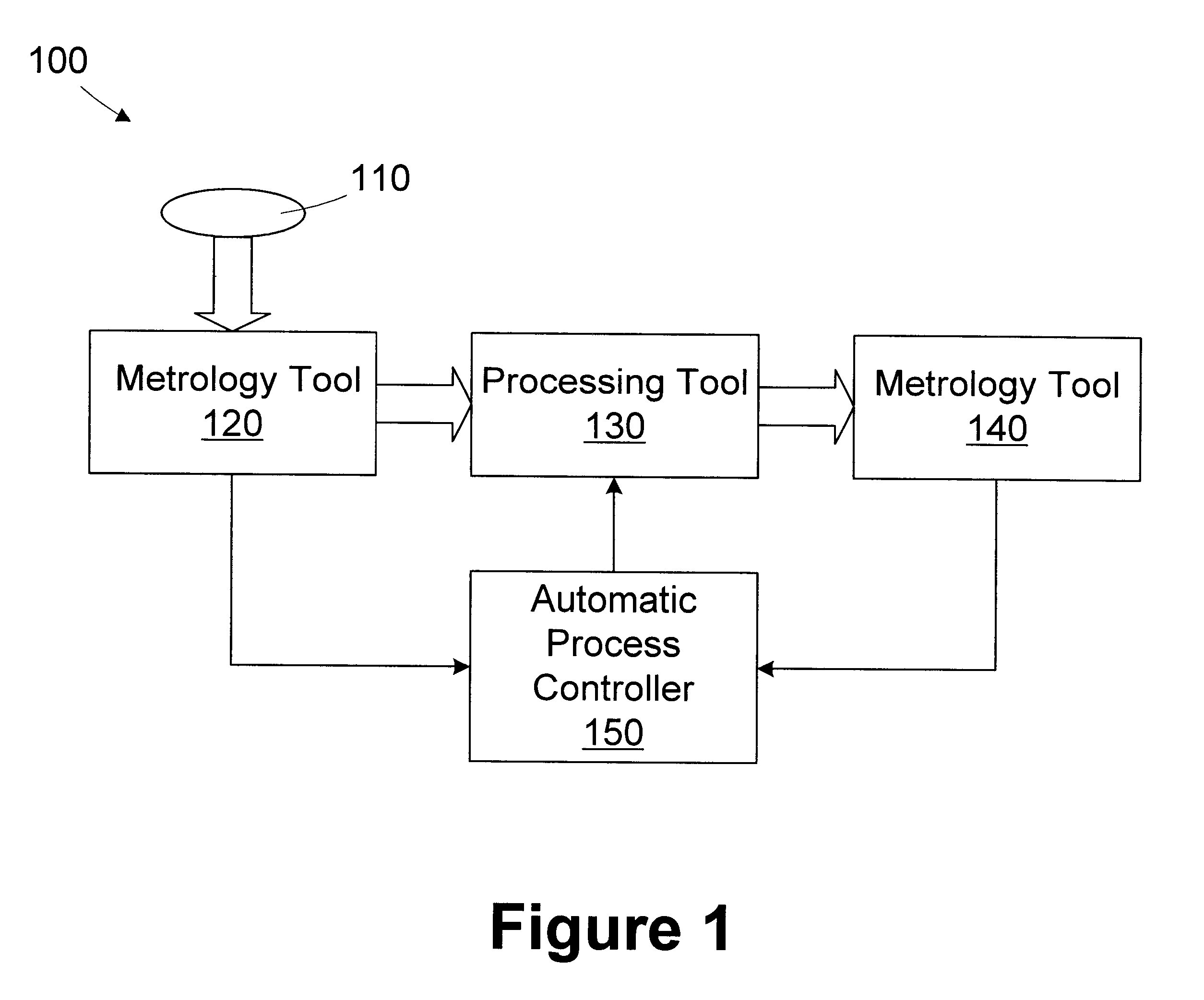
Referring now to FIG. 1, a simplified diagram of a portion of an illustrative processing line 100 for processing wafers 110 in accordance with the present invention is provided. The processing line 100 includes a pre-process metrology tool 120, a processing tool 130, a post-process met...


PUM

PropertyMeasurementUnit
processing rateaaaaaaaaaa
idle timeaaaaaaaaaa
timeaaaaaaaaaa

Abstract

A method for monitoring consumable performance in a processing tool comprises storing a performance model of the processing tool; receiving a consumable item characteristic of a consumable item in the processing tool; determining a predicted processing rate for the processing tool based on the consumable item characteristic and the performance model; determining an actual processing rate of the processing tool; and determining a replacement interval for the consumable item based on at least the actual processing rate. A processing system includes a processing tool and an automatic process controller. The processing tool is adapted to process wafers and includes a consumable item.

Description

1. Field of the InventionThis invention relates generally to semiconductor device manufacturing, and, more particularly, to a method and apparatus for monitoring consumable performance in a processing tool.2. Description of the Related ArtThe manufacture of most devices, such as semiconductor devices, requires a number of discrete processing steps to create the device. With respect to semiconductor devices, a number of discrete steps are needed to produce a packaged semiconductor circuit device from raw semiconductor material. The starting substrate is usually a slice of single crystal silicon referred to as a wafer. Circuits of a particular type are fabricated together in batches of wafers called "lots" or "runs". The fabrication process creates regular arrays of a circuit on the wafers of a lot. During processing, the individual wafers in a lot may go through individual processing steps one at a time or as a batch. At the completion of wafer processing, the wafers are tested to de...

Claims


Application Information

Patent Timeline
Patent Type & Authority Patents(United States)
IPC IPC(8): G05B19/418
CPCG05B19/4184G05B2219/45031G05B2219/32234Y02P90/02Y10T70/5628
Inventor CAMPBELL, WILLIAM J.LANSFORD, JEREMYCONBOY, MICHAEL R.
Owner GLOBALFOUNDRIES US INC
Why Eureka
Try Eureka