Method and apparatus for controlling writing of flash EEPROM by microcomputer

a microcomputer and flash eeprom technology, applied in computing, error detection/correction, instruments, etc., can solve problems such as inability to add external circuitry and unstable operation

a microcomputer and flash eeprom technology, applied in computing, error detection/correction, instruments, etc., can solve problems such as inability to add external circuitry and unstable operation

US6567930B1Inactive Publication Date: 2003-05-20RENESAS ELECTRONICS CORP

Image

  • Method and apparatus for controlling writing of flash EEPROM by microcomputer
  • Method and apparatus for controlling writing of flash EEPROM by microcomputer
  • Method and apparatus for controlling writing of flash EEPROM by microcomputer

Examples


second embodiment

the present invention will now be described.

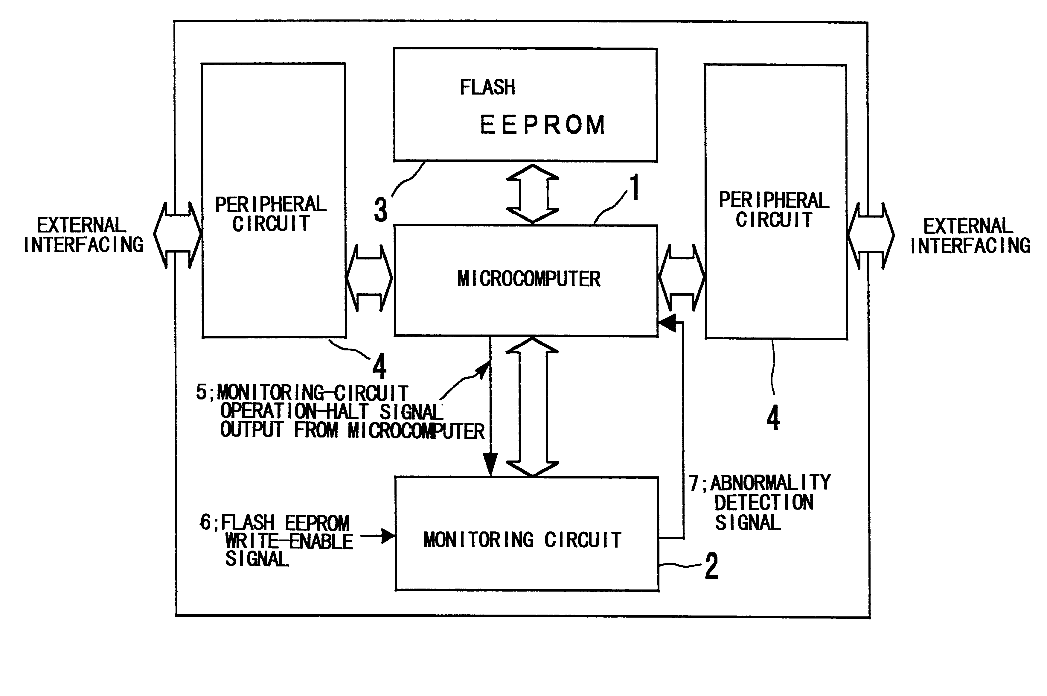
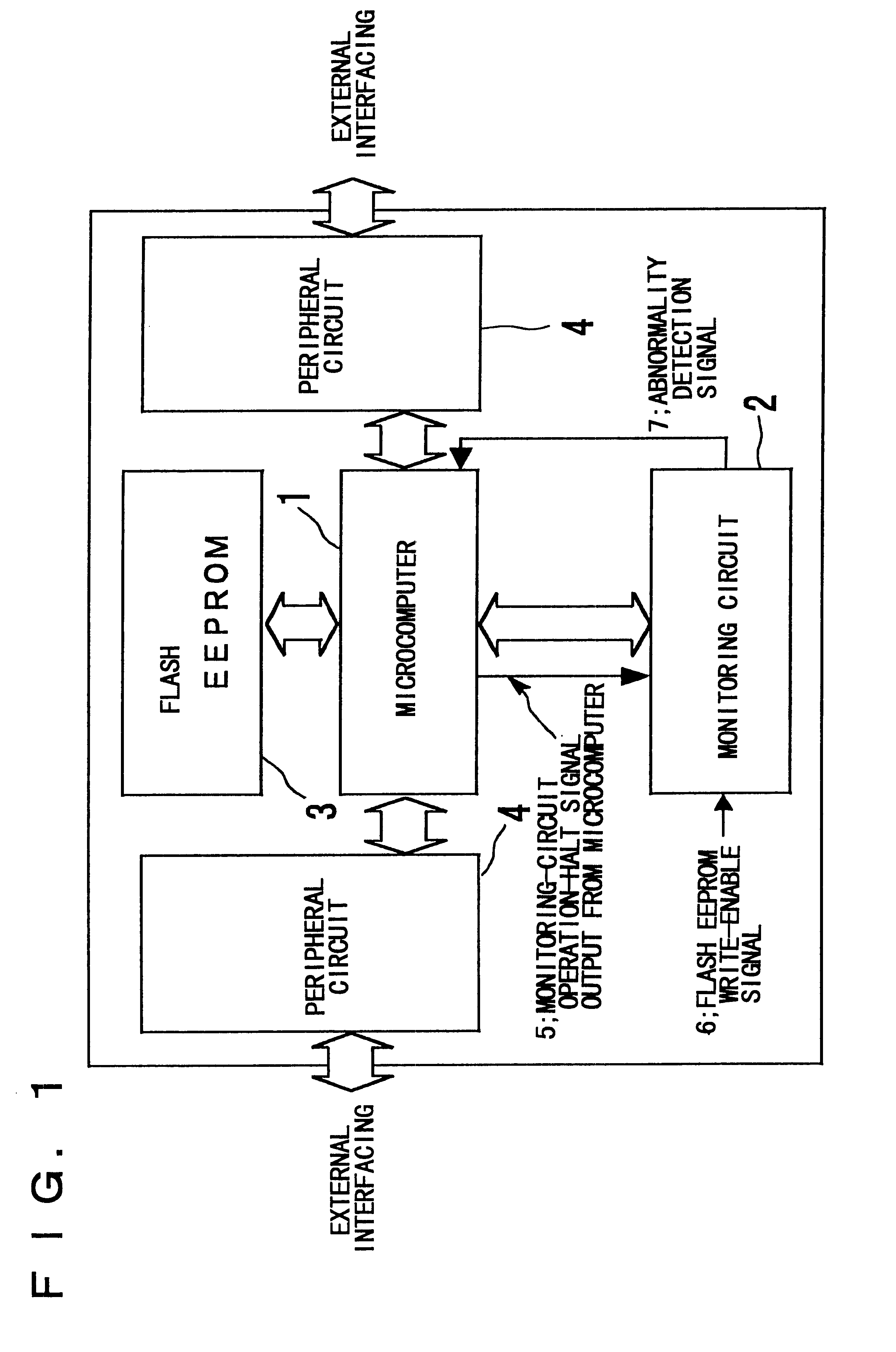
FIG. 3 is a diagram showing an example of a circuit arrangement in which the monitoring circuit 2 of the microcomputer is constituted by a watchdog timer.

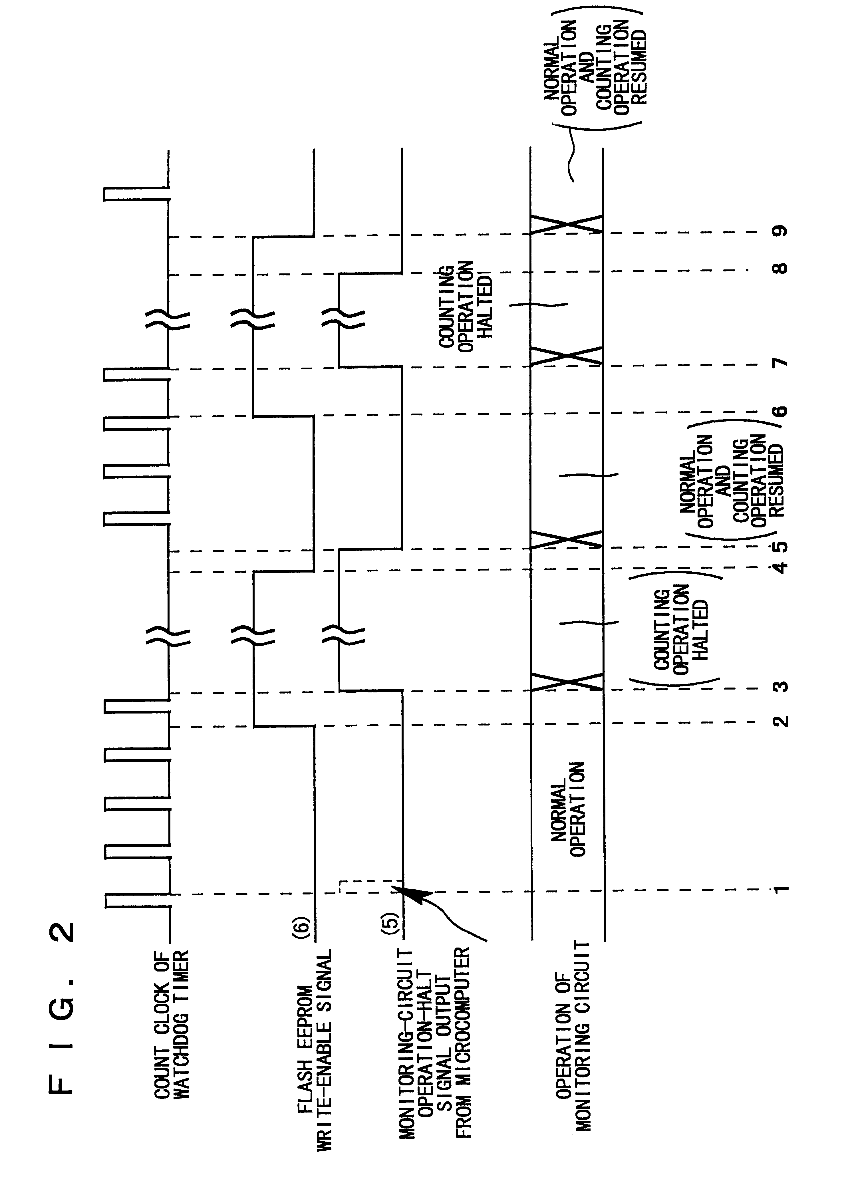
As shown in FIG. 3, an externally entered flash EEPROM write-enable signal (VPP) 6 and a monitoring-circuit operation-control signal (WDSR) 5 output from the microcomputer 1 enter a control circuit (block) 23, which controls the count clock of a watchdog timer 21. On the basis of the VPP signal 6 and WDSR signal 5, the control circuit 23 controls the output of the abnormality detection signal (INTWDT) 7 issued by the watchdog timer 21. The abnormality detection signal (INTWDT) 7 enters the microcomputer 1 as a reset signal or interrupt signal.

The watchdog timer 21 will not stop counting the clock even when the VPP signal 6 is input to the count-clock control circuit 23. In order to halt the counting operation of the watchdog timer 21, the WDSR signal 5 from the microcomputer 1 is set to t...


PUM


Abstract

An apparatus that make it possible for a microcomputer to execute self-programming without the occurrence of shutdown or initialization (restart) includes a flash EEPROM for storing programs and data, a monitoring circuit for monitoring program runaway and malfunction, and the microcomputer. When rewriting of the content of said flash EEPROM (i.e., self-programming) is executed via control by the microcomputer, the monitoring circuit controls output / suppression of an abnormality detection signal on the basis of an externally entered flash EEPROM write-enable signal and a monitoring-circuit operation-control signal output from the microcomputer.

Description

This invention relates to a method and apparatus for writing a flash EEPROM and, more particularly, to a method and apparatus for writing a flash EEPROM by a microcomputer.A microcomputer incorporates a flash-type EEPROM (Electrically Erasable and Programmable Read-Only Memory of a flash-erasure type) to which program code and data have been written, and a monitoring circuit for monitoring program runaway and malfunction in the microcomputer. The monitoring circuit is control led by the microcomputer, which loads the program that has been written to the flash EEPROM into a RAM and then executes the program. The monitoring circuit is adapted to sense program runaway and malfunction in the microcomputer.In a microcomputer of this kind, the microcomputer performs an operation (referred to as "self-programming") in which the content of the flash EEPROM is rewritten by the microcomputer itself. In such case it is necessary to control the operation of the monitoring circuit for the follow...

Claims


Application Information

Patent Timeline
20 May 2003
Publication
US6567930B1
IPC
G06F11/00; G06F11/30; G06F15/78
CPC
G06F11/0751
Inventors
MORIYA, SEIICHI