

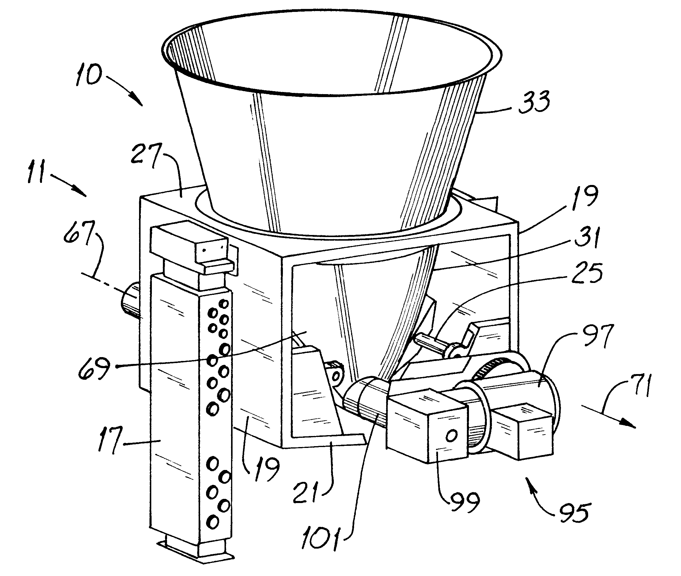
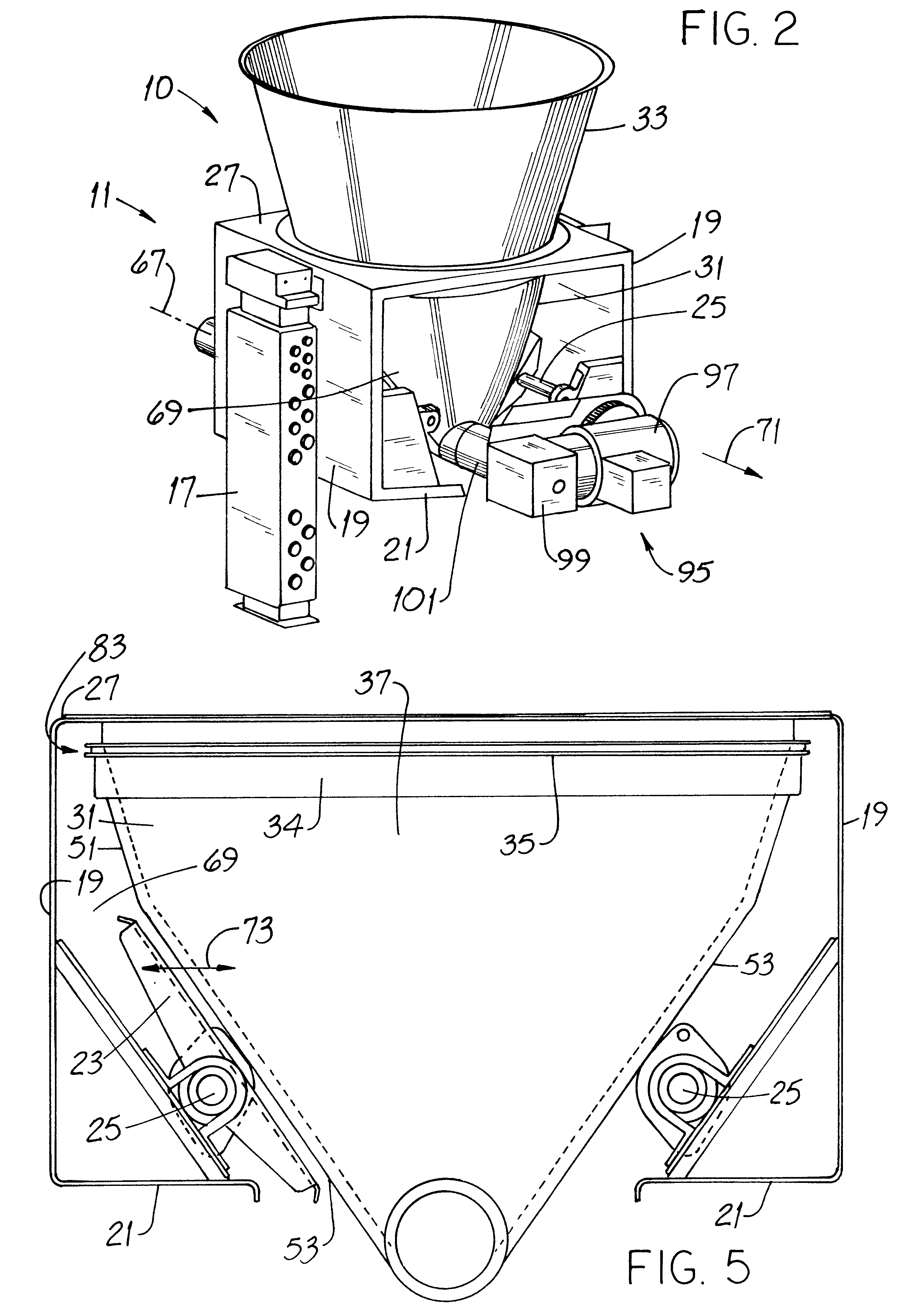
Bulk-solid metering system with laterally removable feed hopper
a metering system and hopper technology, applied in the direction of liquid transfer devices, movable measuring chambers, instruments, etc., can solve the problems of not being able to avail the system value, the rectangular hoppers work poorly at promoting what is known as "mass flow", and the time and effort is very substantial. , to achieve the effect of reducing time and effor
- Summary
- Abstract
- Description
- Claims
- Application Information
AI Technical Summary
Benefits of technology
Problems solved by technology
Method used
Image

Examples
Embodiment Construction
Before describing the new bulk-solid metering system 10, it will be helpful to have an understanding of some aspects of a prior art installation. Once those aspects are understood, the advantages of the invention will be better appreciated.
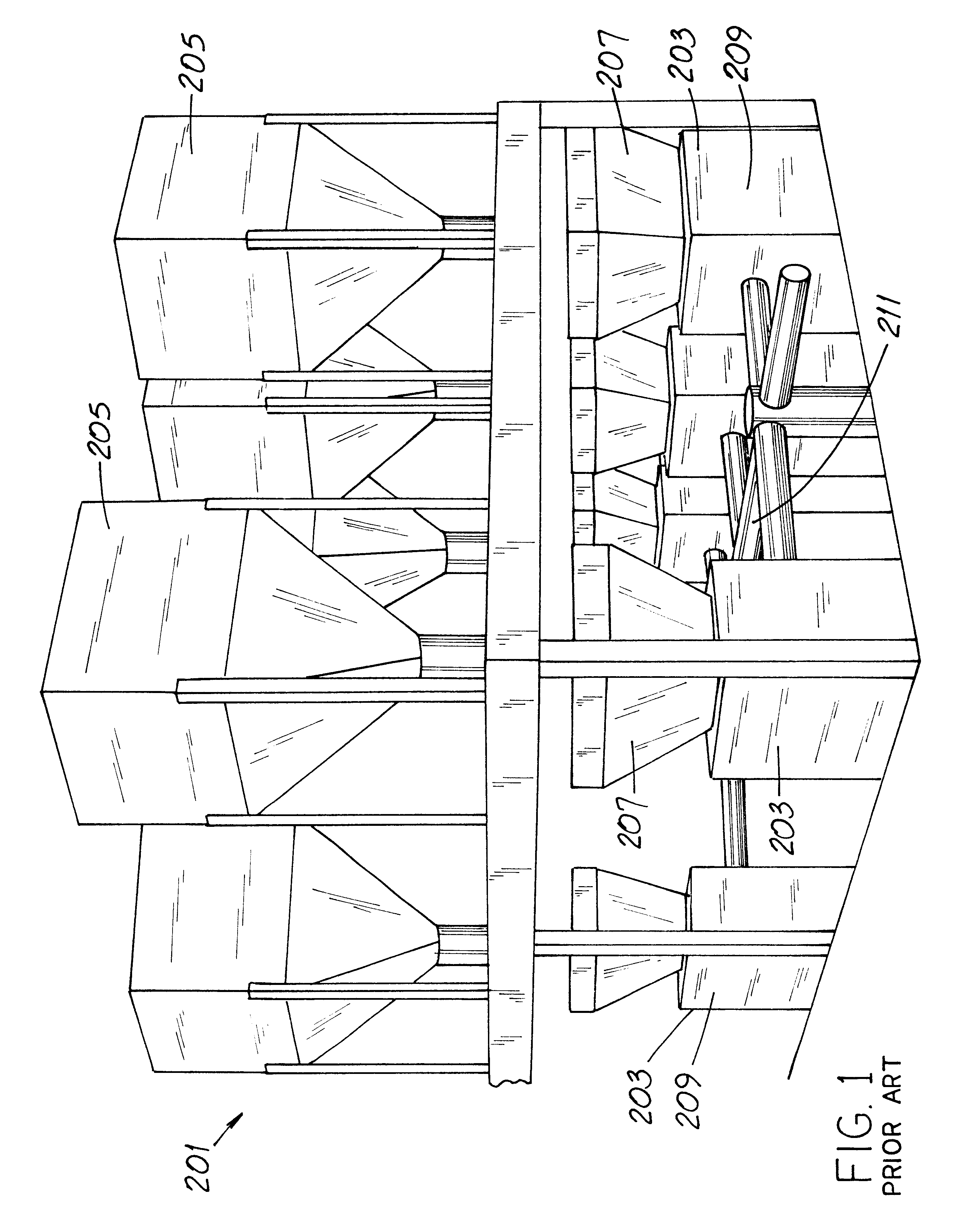
FIG. 1 illustrates a prior art process arrangement 201 which has several bulk-solid metering systems 203 mounted side by side. Each such system 203 includes an auxiliary hopper 205 above a respective system feed hopper 207. The feed hoppers 207 extend downwardly into respective housings 209 and terminate in a spout in which an auger or other conveyor operates. Each auger urges material from a respective feed hopper 207 into a multi-branch pipeline 211 which feeds such material into the process equipment. Such equipment may be, e.g., mixing powder additives for paint, making multi-constituent pelletized products or the like.
From FIG. 1, it is apparent that in order to service a particular system 203 and, more notably, a particular feed hopper 207, ...
PUM
 Abstract
Description
Claims
Application Information