Resolution-enhancement method for digital imaging

a technology of resolution enhancement and digital imaging, applied in the field of resolution enhancement of digital imaging, can solve the problems of difficult implementation, ccd is the single most expensive part of the digital camera, and the cost of both types of cameras is considerable, so as to achieve the effect of increasing resolution

Inactive Publication Date: 2003-05-27
HOWELL
View PDF11 Cites 141 Cited by
  • Summary
  • Abstract
  • Description
  • Claims
  • Application Information

AI Technical Summary

Benefits of technology

to increase resolution without color aliasing.

Problems solved by technology

Often the CCD is the single most expensive part of the digital camera.
Since most studios must photograph both types of scenes, most studios are compelled to own both types of cameras at a considerable financial burden.
First, it is difficult to implement, since the translation device must rapidly and with sub-pixel pitch accuracy displace the array a distance equal to its full width and / or height with repeatable results.
Also, the imaging array must not be displaced in a direction normal to the focal plane or a deleterious focus shift will occur.
This is a very awkward situation since a non-tiled image does not yield a preview of a final higher resolution image but rather only a section of the higher resolution image.
This change of lens is slow, and usually requires re-focusing and resetting the aperture.
While the interstitial shifting technique does increase the effective resolution of the array it suffers from several drawbacks.
As the aperture ratio decreases below 100%, pixel sampling error becomes more and more pronounced.
Thus if one intends to have a low resolution mode as well as a high resolution mode employing interstitial shifting, the quality of the low resolution mode will be compromised by sampling error.
Another drawback of the low aperture ratio interstitial shifting method is compromised pixel sensitivity.
Since a more sensitive pixel is a general design goal by virtue of improved signal-to-noise performance and because a more sensitive imager is generally desirable for well known reasons, CCD's with small aperture ratios are not as desirable for still photography as those with aperture ratios approaching 100%.
A further drawback of the low-aperture-ratio interstitial-shifting method is that the degree of resolution-enhancement that can be achieved depends on the aperture ratio.
While there is much in the prior art describing approaches that shift arrays using the interstitial method, there is very little describing the overlapped shifting, or sub-pixel-shifting, approach.
Also, the cited prior art fails to address the problem of color aliasing.
Color aliasing problems potentially exist for all camera configurations that use local color filtering of the sensing matrix unless specific anti-aliasing techniques are employed.
Color aliasing is most troublesome when the spatial frequency of the image formed on the CCD (or other his type of imager) meets or exceeds the Nyquist frequency of the imager (1 / 2 the sampling spatial frequency).
Furthermore, color aliasing reduces the usable resolution of a CFA below what would be expected from the size of the array.
Of course other interpolation schemes are possible, but no interpolation scheme can overcome the fact that the CFA records only a fraction of all the information needed to faithfully record a color image at a spatial frequency approaching the Nyquist frequency of the CFA.
Higher bit depths allow more faithful tonal reproduction, lower bit depths in the extreme can lead to overly quantized tonal reproduction ("posterization").
Color aliasing can be attacked by holding the spatial frequency of the image below the Nyquist frequency of the imager (by using a form of blurring filter, for example), but the tradeoff expressed above forces a resolution loss.
Resolution-enhancement loses value now since there is little additional image information available anyway.
If no blurring filter is used, then the problem of color aliasing deflates the resolution-enhancement achieved and one is left with the problem of false color.

Method used


Image

  • Resolution-enhancement method for digital imaging
  • Resolution-enhancement method for digital imaging
  • Resolution-enhancement method for digital imaging

Examples


Embodiment Construction

Array Movements and Modes

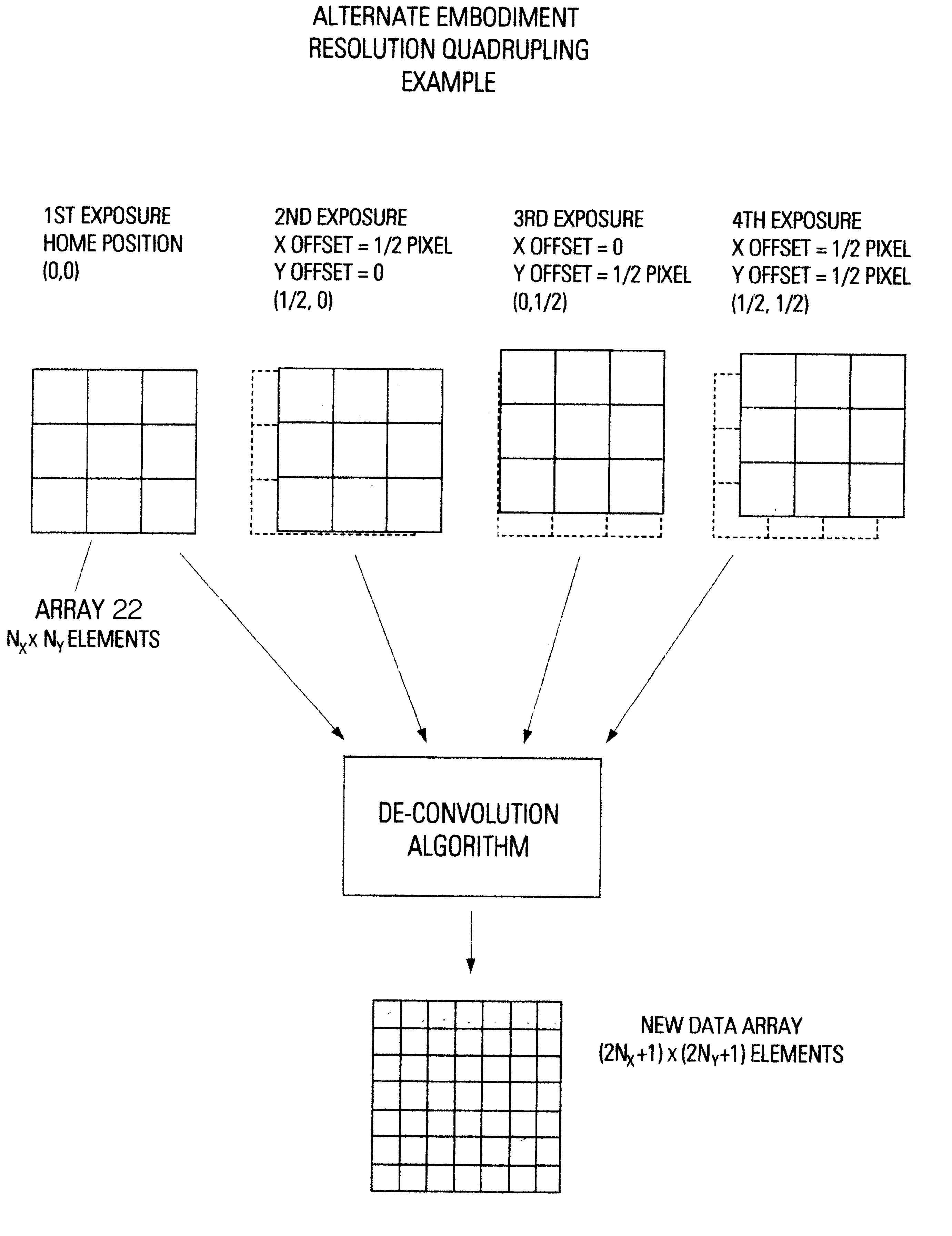
A description of array movements and modes according to the alternate embodiment is shown in FIG. 10. Starting at a home position, a first exposure is taken with the global filter 20 arbitrarily set to red, the order of color being filtered having no bearing on the final outcome. The unfiltered large-aperture-ratio array 22 records the red-filtered scene, and the data is stored according to methods common in the art. Next, array 22 is displaced from the home position a distance laterally (the X direction) equal to one-half the pixel pitch of array 22. Array 22 again records the red-filtered scene and the data is again stored. Next, the array is moved from the home position (0,0) to a position displaced one-half pixel in the Y direction (0,1 / 2), the array 22 is again exposed and the data stored. Finally, the array is displaced by one-half pixel in both the X and Y direction (1 / 2, 1 / 2), again exposed, and the data recorded. The four sets of data produced conta...


PUM


Abstract

A method for resolution enhancement of a still-image made by a digital imaging device. The method allows the use of high-aperture-ratio sensing arrays that produce resolution-enhancement, independent of the angle of view. Resolution-enhancement is achieved using a multiple-exposure technique of a sub-pixel overtap in conjunction with a whole-pixel shift. The method suppresses color-aliasing in a multiple-exposure native-resolution mode and enables the use of a single camera for single-exposure and multiple-exposure modes.

Description

1. Field of the InventionThe present invention relates to devices and methods to increase the effective resolution of an array of spaced-apart light-sensitive transducers used to record an image in a digital imaging device.2. Description of the Prior ArtDevices that record a visual scene by using an array of photoelectric sensors are well known in the art. Such a device configured as a scanner may be used to record digitally an existing transparency or print, or, in the form of a camera, may record a scene. The photoelectric-sensor array is typically a charge-coupled device (CCD) that outputs analog information that, in turn, is commonly digitized through the use of an analog-to-digital converter (ADC) and stored as bits of data in computer memory or other form of electronic storage. For this discussion we will refer to camera-type devices utilizing CCD array sensors, though the principles laid out here apply equally well to cameras constructed with other types of photoelectric sens...

Claims


Application Information

Patent Timeline
Patent Type & Authority Patents(United States)
IPC IPC(8): H04N9/04H04N3/15H04N1/028H04N5/217H04N5/225H04N5/349H04N5/372H04N9/07
CPCH04N9/045H04N3/1587H04N25/48H04N23/843H04N25/134
Inventor HOWELL, PAUL
Owner HOWELL
Why Eureka
Try Eureka