

Cleaning and drying method and apparatus
a technology of cleaning and drying method and apparatus, which is applied in the direction of data recording, cleaning using liquids, instruments, etc., can solve the problems of increasing the size of the apparatus, increasing the amount of drying gas consumed, and lowering the drying efficiency
- Summary
- Abstract
- Description
- Claims
- Application Information
AI Technical Summary
Problems solved by technology
Method used
Image

Examples
first embodiment
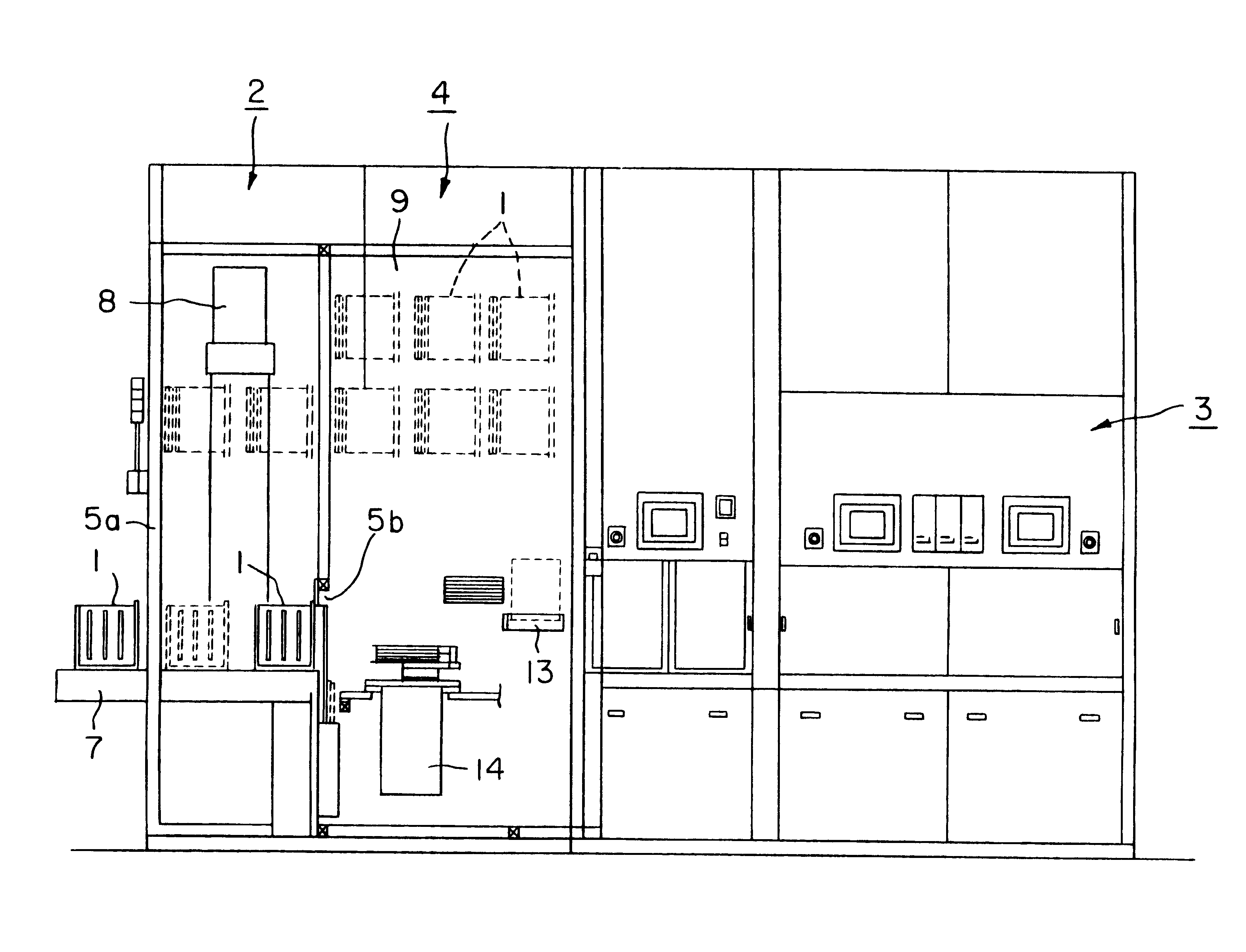
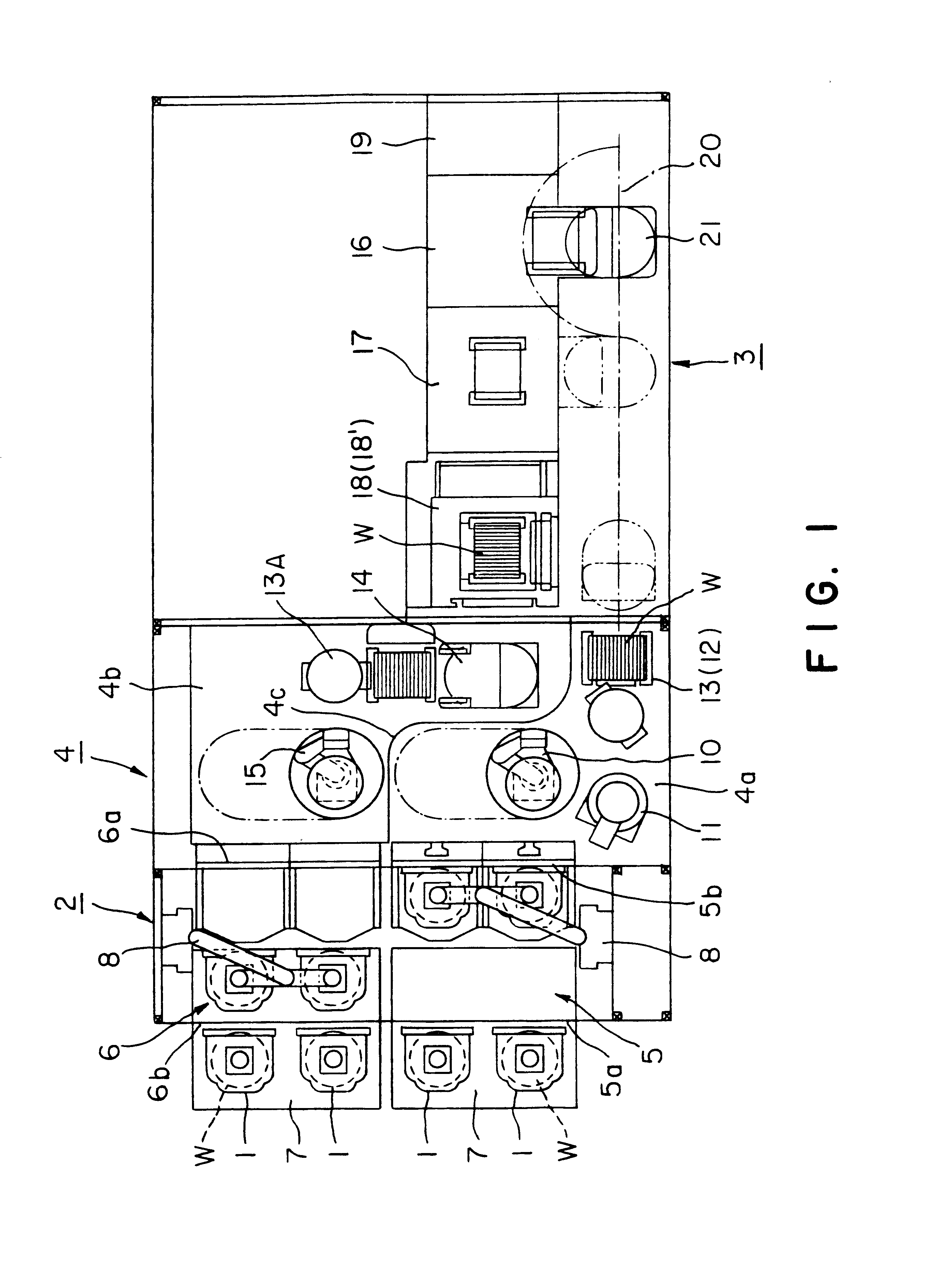
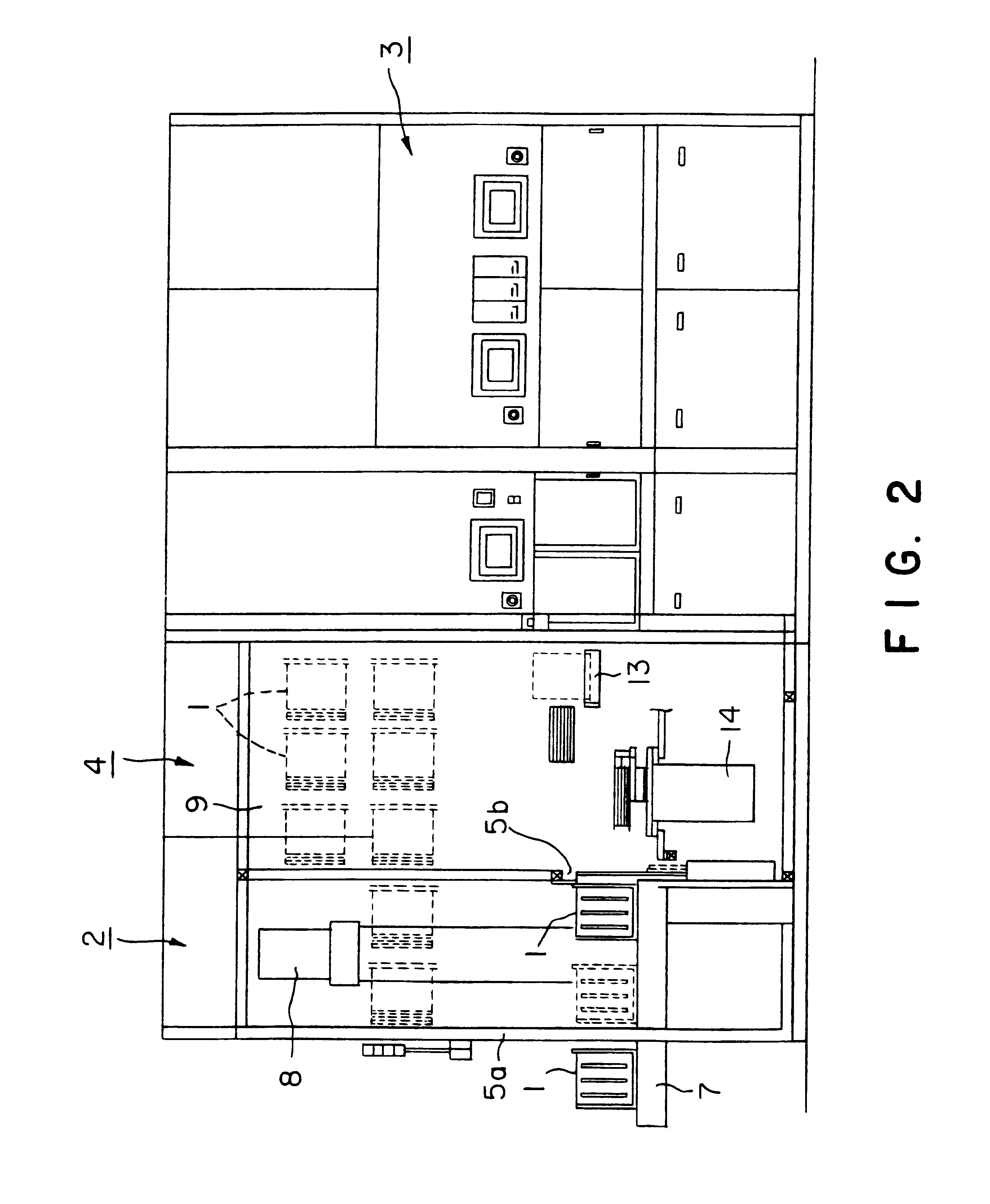
The description now turns to the cleaning and drying apparatus of the present invention, with reference to FIGS. 3 and 13.
The cleaning and drying apparatus 18 has a cleaning tank 22 (cleaning chamber) which is filled with a chemical such as hydrofluoric acid and a rinse (cleaning liquid) such as distilled water, where the wafers W are immersed in this chemical and cleaning liquid; and a drying chamber 23 positioned above the cleaning tank 22. The cleaning and drying apparatus 18 also has a wafer boat 24, in other words a first holder device, for holding a plurality of wafers W, such as 50 wafers W, and moving them between the cleaning tank 22 and the drying chamber 23.
The cleaning tank 22 has an inner tank 22a formed of a material such as quartz or polypropylene and an outer tank 22b disposed on the outer side of an upper portion of the inner tank 22a, for stopping any overflowing cleaning liquid from the inner tank 22a.
Chemical / cleaning liquid supply nozzles (hereinafter called liq...
second embodiment
The description now turns to the cleaning and drying apparatus of the present invention, with reference to FIGS. 15 to 25.
FIG. 15 is a cross-sectional view of the cleaning and drying apparatus of this second embodiment and FIG. 16 is a side sectional view thereof. As shown in these figures, the elements configuring a cleaning and drying apparatus 18' of this embodiment are the same as those of the cleaning and drying apparatus 18 of the first embodiment, concerning the cleaning chamber 22 and the box 30. Identical elements are given the same reference numbers.
The description below concerns the configuration of a drying chamber 123. The drying chamber 123 is defined by an enclosure 123A which is made of quartz and is U-shaped in section. An aperture 123a that communicates with an aperture in an upper portion of the cleaning tank 22, with a shutter 136 therebetween, is formed in the enclosure 123A, drying gas supply nozzles 137 are disposed on both sides of an upper portion of the int...
PUM
| Property | Measurement | Unit |
|---|---|---|
| relative vertical movement | aaaaa | aaaaa |
| vertical relative movement | aaaaa | aaaaa |
| volatile | aaaaa | aaaaa |
Abstract
Description
Claims
Application Information