Method and apparatus for mismatched shaping of an oversampled converter

Inactive Publication Date: 2003-06-10
AVAGO TECH INT SALES PTE LTD
View PDF9 Cites 25 Cited by
  • Summary
  • Abstract
  • Description
  • Claims
  • Application Information

AI Technical Summary

Problems solved by technology

However, multi-bit modulators typically require multi-bit DACs with highly linear performance.
The linearity of a multi-bit DAC is typically limited by how precise analog elements, such as capacitors, resistors or current sources, can be matched.
However, the digital complexity of such a method increases tremendously with the number of bits in the digital

Method used


Image

  • Method and apparatus for mismatched shaping of an oversampled converter
  • Method and apparatus for mismatched shaping of an oversampled converter
  • Method and apparatus for mismatched shaping of an oversampled converter

Examples


first embodiment

C. Summary of First Embodiment

V. Second Embodiment of Mismatch Shaping Network

A. High Level Overview of Second Embodiment

B. First Implementation

C. Second Implementation

D. Variations on Second Embodiment

VI. Flow Diagrams

VII. Conclusion

The following description is of the best modes presently contemplated for practicing the invention. This description is not to be taken in a limiting sense but is made merely for the purpose of describing the general principles of the invention. The scope of the invention should be ascertained with reference to the claims. In the description of the invention that follows, like numerals or reference designators will be used to refer to like parts or elements throughout.

I. EXEMPLARY ENVIRONMENTS

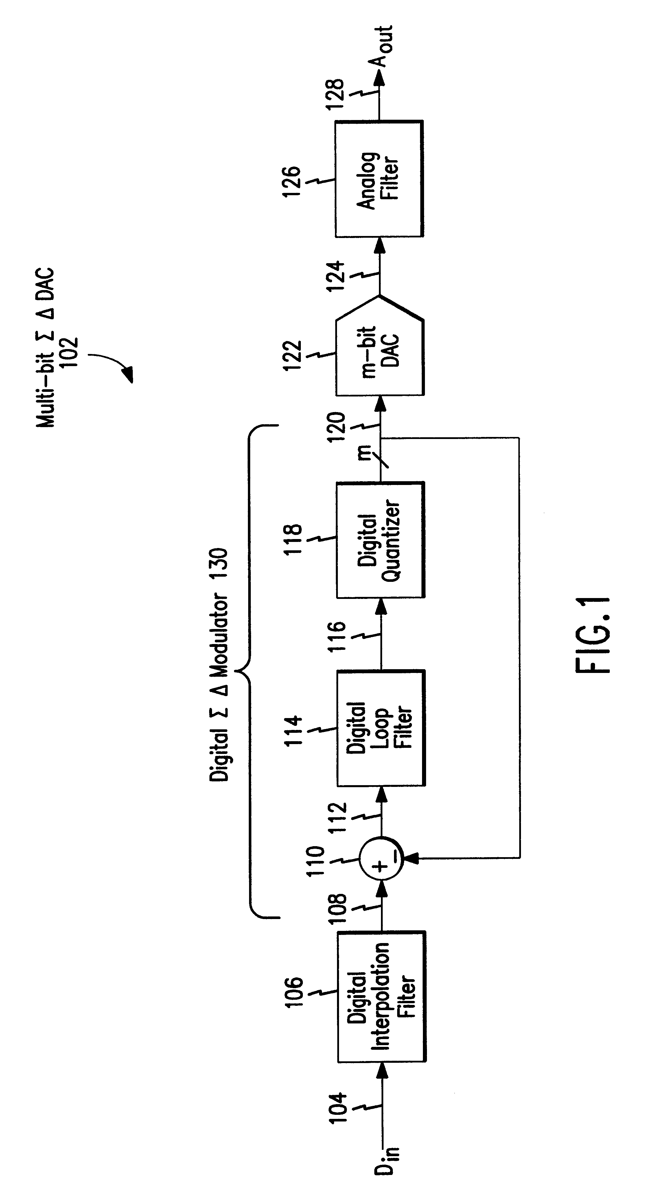
FIG. 1 shows an exemplary environment in which the present invention is useful. More specifically, FIG. 1 shows an exemplary multi-bit sigma-delta (.SIGMA..DELTA.) digital to analog converter (DAC) 102. Multi-bit .SIGMA..DELTA. DAC 102 includes a digital interpolat...

third embodiment

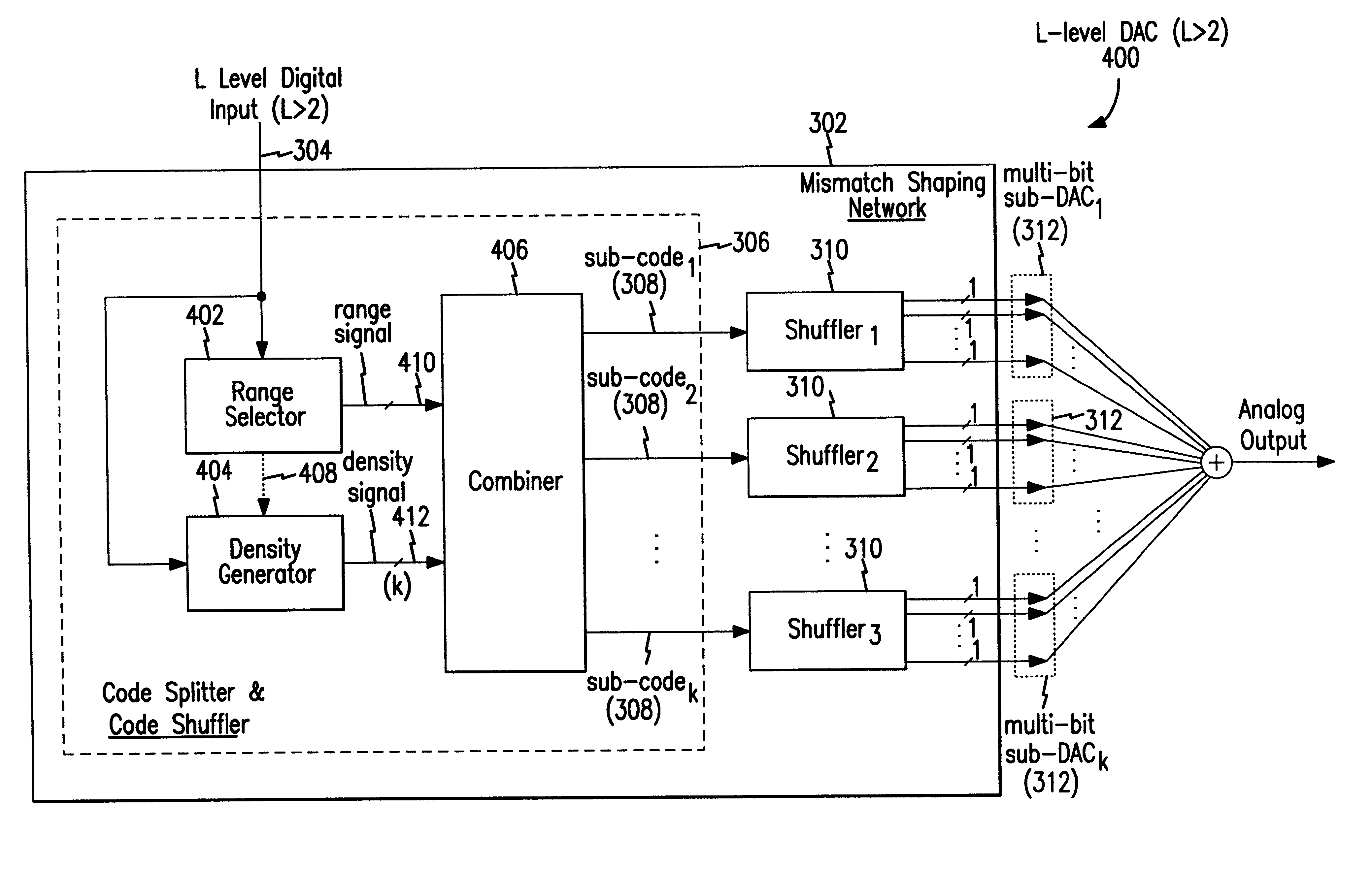
A first implementation of the mismatch shaping network 302 will be described with reference to FIG. 14. In the first implementation of FIG. 14, digital input signal 304 is a sixteen (16) level input signal that can be equal to binary 0000 (decimal 0) through binary 1111 (decimal 16). In a second implementation, described with reference to FIG. 15, digital input signal 304 is a seventeen (17) level input signal that can be equal to binary 00000 (decimal 0) through binary 10000 (decimal 17).

B. First Implementation

Referring to FIG. 14, digital input signal 304 (also referred to as x) is a sixteen (16) level input signal that can be equal to binary 0000 (decimal 0) through binary 1111 (decimal 16), as just mentioned above.

In this embodiment, the function of truncation block 1302 is accomplished by simply taking the two MSBs (i.e., x) of digital input signal 304 to produce range signal 1304. As mentioned above, range signal 1304 is an implementation of range signal 410.

Similarly, the fun...

second embodiment

D. Variations on Second Embodiment

In the above described implementations of the second embodiment of mismatch shaping network 302, shuffler 1310 is used to move the effects of errors produced by the multi-element sub-DACs to out of band frequencies. As mentioned above, shuffler 1310 can be implemented using the shuffler described above in detail with reference to FIG. 6. Alternatively, any dynamic element matching (DEM) algorithm known in the art (and its corresponding implementation) can be used in place of shuffler 1310 to spectrally shape the gain mismatch errors. Referring to FIG. 13, for example, if the multi-bit DAC 300 is constructed from of K multi-element sub-DACs 312, any K-element DEM encoder can be used in place of shuffler 1310.


PUM


Abstract

Methods and apparatuses for spectrally shaping mismatch errors in a multi-bit digital to analog converter (DAC). In an embodiment, a range signal is produced based on the digital input code. The range signal specifies which one of a plurality of ranges the digital input code is within. A density code is also produced, preferably, using a shuffling algorithm. The density code specifies a level within the range expressed by the range signal. The range signal and the density code are then combined to produce a plurality of sub-codes, a sum of the plurality of sub-codes equaling the digital input code.

Description

1. Field of the InventionThe present invention relates to sigma-delta digital to analog converters (DACs), and more particularly to methods and apparatuses for mismatch shaping of an oversampled converter. Even more specifically, the present invention relates to mismatch shaping networks for use in multi-bit DACs.2. Background ArtIt is known to process analog signals using digital circuitry. Typically, such circuitry converts analog signal to binary values, arithmetically manipulates the binary values with binary circuitry to perform filtering and digital signal processing, and then converts the processed binary values back into analog signals (e.g., for sound reproduction). To minimize the circuitry required to convert the analog signals to binary values, sigma-delta modulators are often utilized.Sigma-delta modulators sample the analog signal at a rate that is orders of magnitude greater than the highest frequency present. Sigma-delta modulators use the technique of oversampling a...

Claims


Application Information

Patent Timeline
IPC IPC(8): H03M1/06H03M1/74
CPCH03M1/067H03M1/74H03M3/502H03M3/464H03M1/742
Inventor BROOKS, TODD L.HO, DAVID S. P.MILLER, KEVIN L.FOGLEMAN, ERIC
Owner AVAGO TECH INT SALES PTE LTD
Why Eureka
Try Eureka