Construction layout block

a construction layout and layout technology, applied in the field of layout blocks, can solve the problems of insufficient time, inability to accurately and accurately propagate additional errors into the layout, and inability to accurately and accurately measure the distance between layout lines, so as to facilitate the striking of arcs quickly and accurately, and the degree of accuracy and efficiency is high.

Inactive Publication Date: 2003-06-17
TANGO JR RONALD M +1
View PDF37 Cites 52 Cited by
  • Summary
  • Abstract
  • Description
  • Claims
  • Application Information

AI Technical Summary

Benefits of technology

Significantly, by the invention, a construction site or building can be laid out by one man, and this with a high degree of accuracy and efficiency. The contrivance capable of holding a tape measure by its distal end can greatly facilitate measurement of distances from layout lines, walls, and so forth, and suitably embodied can greatly facilitate the striking of an arc quickly and accurately. The built-in laser target sight can facilitate the layout as well. Thus, whereas with the customary methods it can take two men one or two days to layout a building site, with the present invention the layout of the same building site may take one man one day. The invention is simple to make, and simple and accurate to use, and durable as well as practical.

Problems solved by technology

Such methods, by requiring manual measurements at the distal end of the chalk line, inherently have a propensity to introduce error into the layout.
Moreover, the first method takes a relative abundance of manpower to accomplish, and the second, although it would reduce the manpower required to do the job, is cumbersome to carry out and by its clumsiness can both take an inordinate amount of time and propagate additional errors into the layout.
Although that arc-making technique is fairly adequate for many applications, difficulties arise in accurately setting the nail, as if it is not set right the first time moving it close by the first attempt can be difficult if not impossible owing to the first nail hole, and in being able to strike an arc over a floor type surface into which a nail cannot or should not be placed, for example, in dirt, concrete or a finished hardwood floor.
The foregoing art, however, does not provide a basic, convenient, practical solution to the aforementioned problems in the art of construction layout, and, the present invention aside, there remains in the art a long-felt need to effectively address and ameliorate, if not completely overcome, such problems and other difficulties known generally in the art of construction layout.

Method used


Image

  • Construction layout block
  • Construction layout block
  • Construction layout block

Examples


Embodiment Construction

The drawings form part of the specification hereof. With respect to the drawings, which are not necessarily drawn to scale, the following exemplary matter is briefly noted:

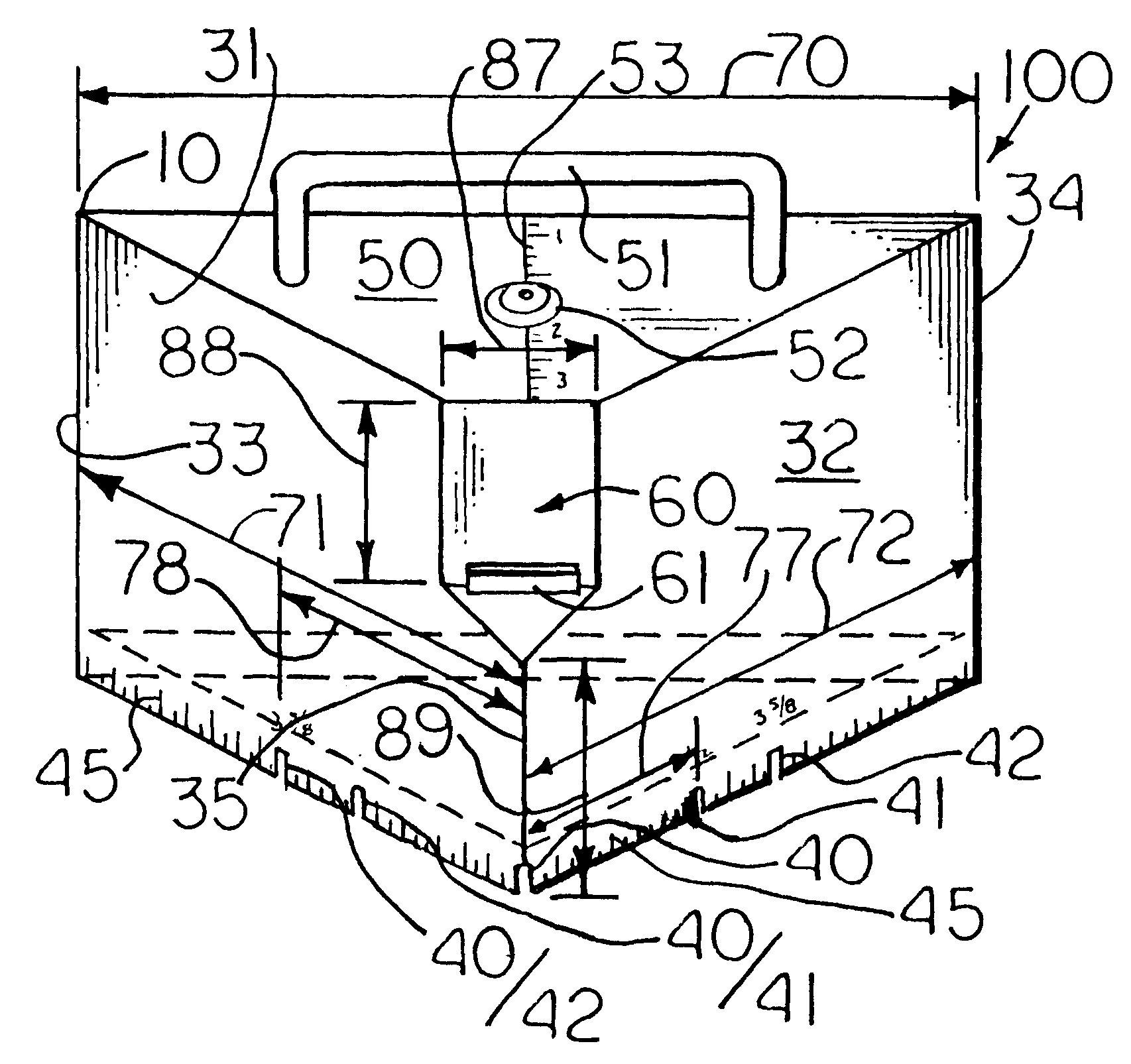
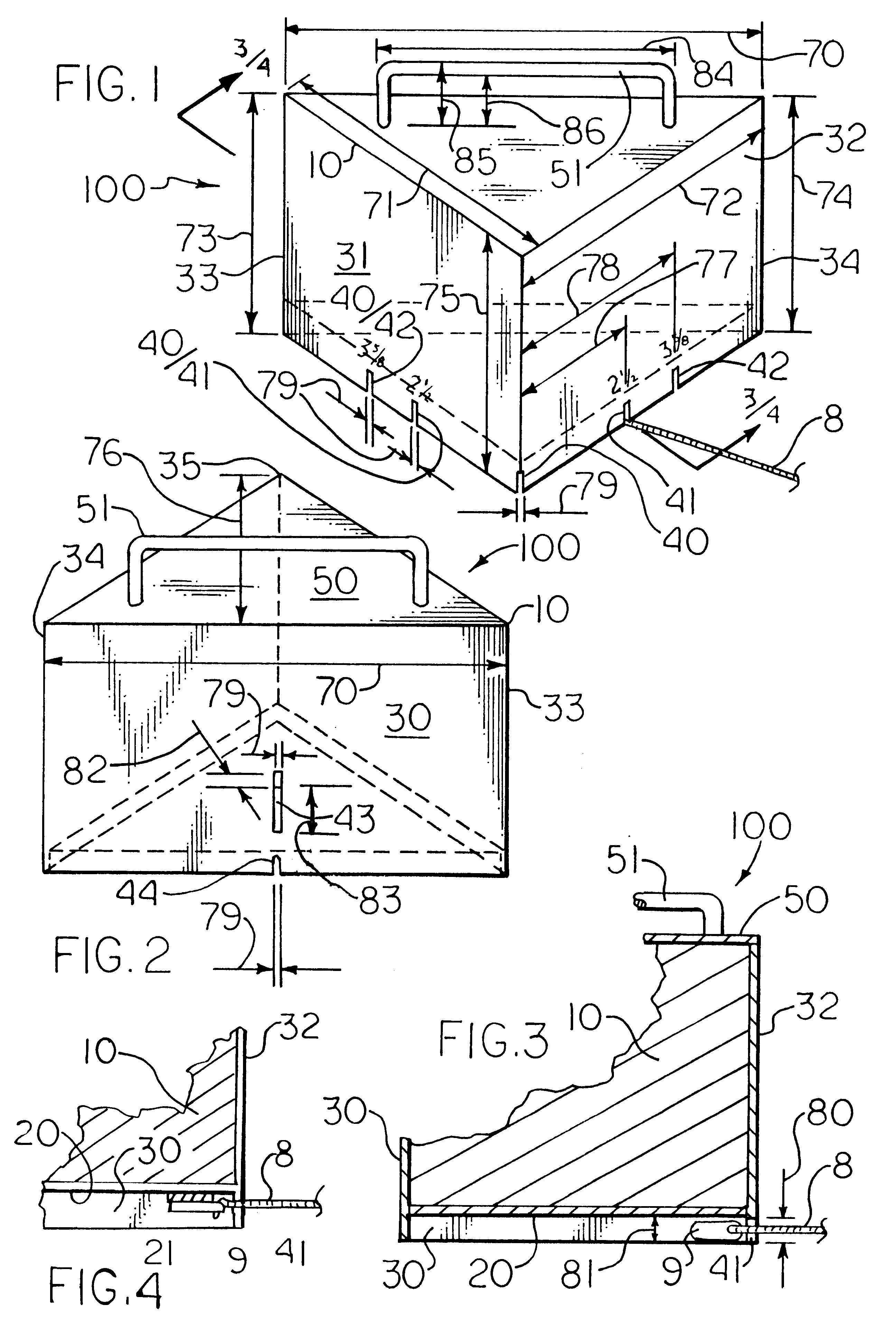
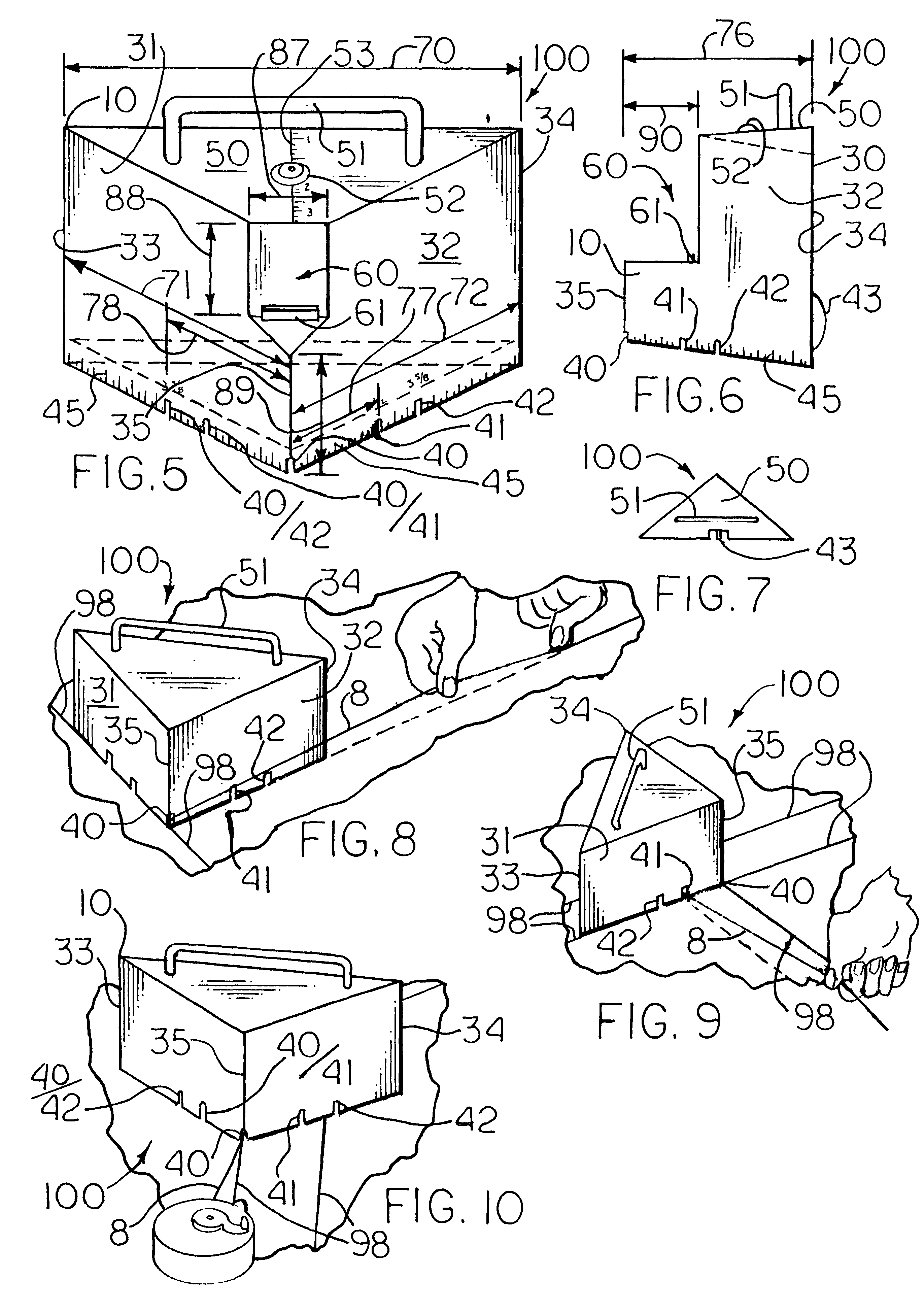
FIG. 1 is a front, top perspective plan view of a triangularly shaped construction layout block of the invention including contrivances for holding a tape measure by its distal end, and an intrinsic laser sight. This layout block also contains additional features including additional artifices for holding a chalk line, a ruler scale, a handle, and a level.

FIG. 2 is a rear, top perspective plan view of the block of FIG. 1, which shows an additional feature of a rear reference system including a notch and a sighting fin, the fin being generally rectangular in shape.

FIG. 3 is a sectional view of the block of FIGS. 1 & 2, taken along 3 / 4--3 / 4 from FIG. 1.

FIG. 4 is a sectional view of another embodiment of a block as of FIGS. 1 & 2 with a magnet to attract a chalk line with a ferrous end, also taken along 3 / 4--3 / 4 in F...


PUM


Abstract

Construction layout block can be provided with a triangularly shaped body with a triangular bottom; a base wall and two side walls extending up from the bottom; base wall junctures formed about intersections of the base wall and the side walls, and an apex juncture formed about intersections of the side walls. It may have one or more of an artifice capable of holding a chalk line; top, with a top carrying handle; a laser target notch; a rear reference system; a top alignment system; a ruler scale; an intrinsic level; and a contrivance for holding a tape measure by its distal end. The block has relative immovability, in general, to resist the force of pulling on a chalk line with the same attached to the block during layout. A construction layout block of any shape may be plastic-coated.

Description

BACKGROUND TO THE INVENTIONI. Field of the InventionThe present invention concerns a layout block useful for laying out a building plan onto a construction site or building. The block, in general, can include a built-in chalk line notch or notches, and it can include a laser sighting feature and / or an arc-drawing guiding pin, a tape measure notch, and so forth. In a particular embodiment, the block has a triangular shape.II. Problems and Known ArtIn the customary practice of laying out a building plan onto a construction site or building, a job typically takes two men: one who holds the distal end of a chalk line at a predetermined place on the site or building, and another who holds the proximal end of the chalk line at another predetermined place; upon proper alignment of the chalk line, it is snapped, and a first layout line is made. A second layout line parallel to the first is then laid out and snapped. This method is repeated until the site or building layout is complete. In a...

Claims


Application Information

Patent Timeline
Patent Type & Authority Patents(United States)
IPC IPC(8): E04G21/18B44D3/38
CPCE04G21/1825B44D3/38
Inventor TANGO, JR., RONALD M.FORTIER, RAYNALD L.
Owner TANGO JR RONALD M
Why Eureka
Try Eureka