
Optical channel selector

a selector and optical channel technology, applied in multiplex communication, electromagnetic repeaters, instruments, etc., can solve the problems of interference (crosstalk) between the filter architecture and the transmission capacity of single channel optical communication systems, difficult fabrication, and difficult interfering with each other

Inactive Publication Date: 2003-06-17
LUCENT TECH INC +1
View PDF6 Cites 29 Cited by
  • Summary
  • Abstract
  • Description
  • Claims
  • Application Information

AI Technical Summary

Problems solved by technology

Consequently, the transmission capacity of single channel optical communication systems is limited to about 2.5 Gbits / sec.
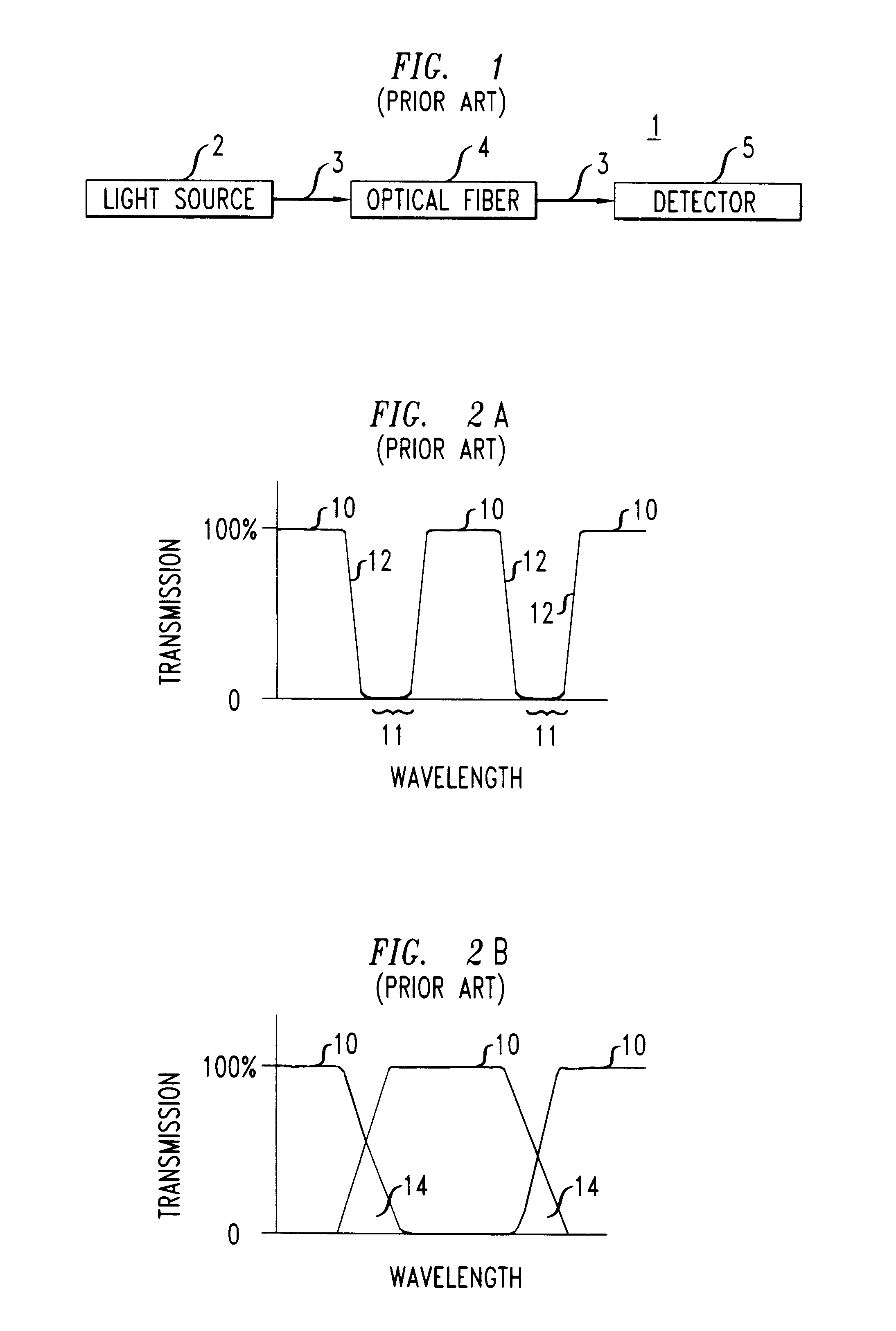
When the passband of the channel selector does not have cut-off regions with steep slopes adjacent channels potentially interfere (crosstalk) with each other.
Such a filter architecture is complex and difficult to fabricate since a large number of MZIs are needed for channel selection.
The desired phase response is applied to the split portions of the multi-channel optical signals so the channels therein interfere with each other either constructively or destructively when the split portions of the multi-channel optical signals are combined.
Phase-shifted channels which have approximately the same phase constructively interfere with each other when the sum of their magnitudes is greater than zero.
Phase-shifted channels destructively interfere with each other when the sum of their magnitudes approximates zero.
The desired phase response is applied to the split portions of the multi-channel optical signals so the channels therein interfere with each other either constructively or destructively when the split portions of the multi-channel optical signals are combined.
Thereafter, when the channels in each optical path are combined, channels having approximately the same phase, constructively interfere with each other.
Channels having phases which differ from each other as a function of .pi., destructively interfere with each other because the sum of their magnitudes approximates zero.
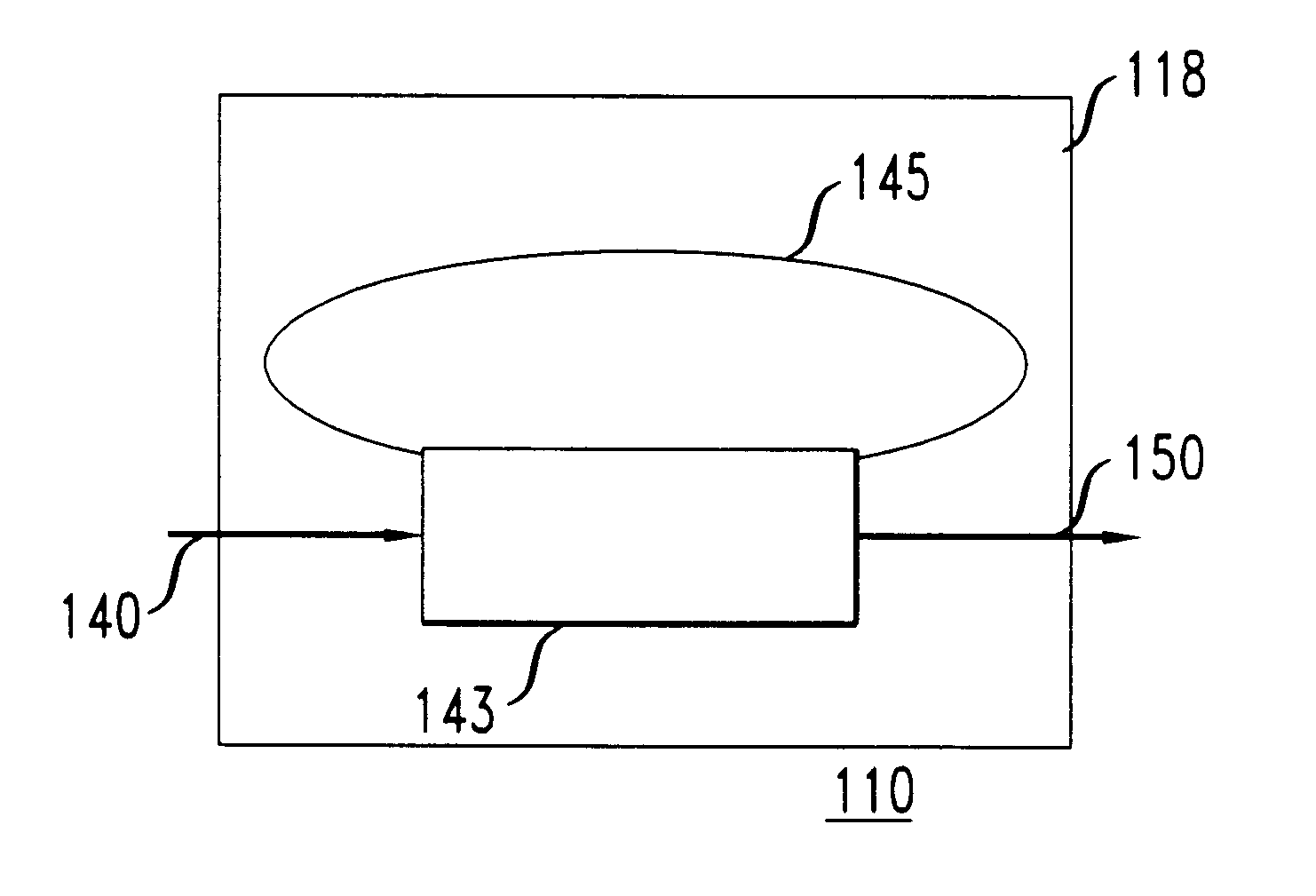
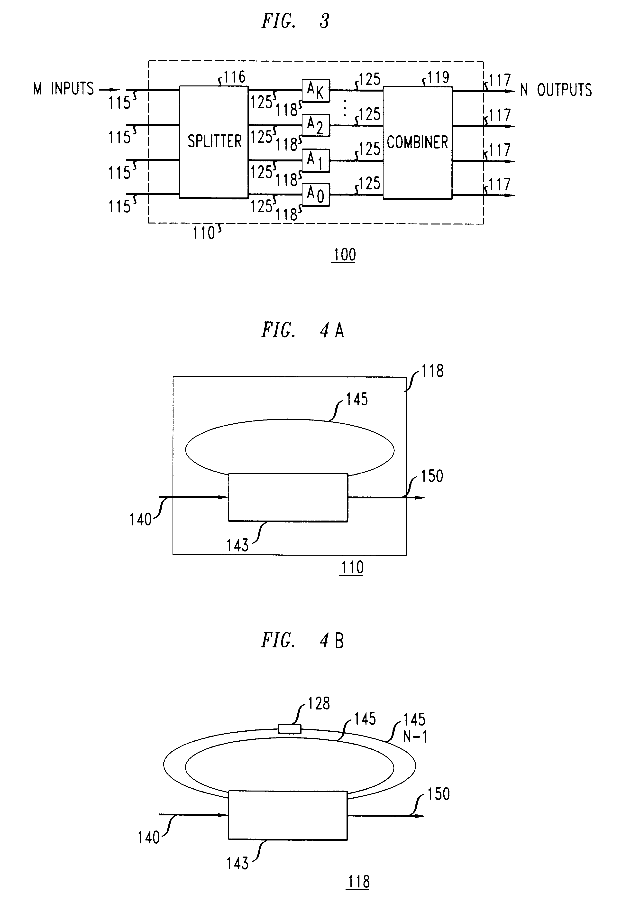
That is, the leading edge portions of the multi-channel optical signal circulating in the feedback path interfere with the trailing edge portions of such optical signal being input thereto.

Method used


Image

  • Optical channel selector
  • Optical channel selector
  • Optical channel selector

Examples


example 2

FIG. 12 depicts a 4.times.4 channel selector with all-pass filters 400 positioned on each optical path 403 connecting two multi-mode interference (MMI) couplers 405. Each optical path 403 has a different path length denoted as 0L, 1L, 2L, and 3L. The all-pass filters 400 in each optical path 403 flatten the passband response of the channel selector without increasing the passband loss. FIG. 13A is a graph of the spectral response for the channel selector shown in FIG. 12. In FIG. 13A the frequency response for each output corresponds to H.sub.1, H.sub.2, H.sub.3, and H.sub.4. The passband of each output response has a peak transmission range that is flat, denoted as 415 on FIG. 13A.

For comparison purposes a graph of the spectral response of a 4-stage filter without all-pass filters, is shown in FIG. 13B. The peak transmission ranges of H.sub.1, H.sub.2, H.sub.3, and H.sub.4 in FIG. 13B, lack passband flatness when compared to the peak transmission ranges of FIG. 13A. Additionally, t...

example 3

A filter with a linear square magnitude response over a frequency range of 0.15.ltoreq..nu..ltoreq.0.85 was designed. The filter is a MZI with a single stage all-pass filter in each arm. The pole magnitudes and phases for the all-pass filters are 0.2925.angle.0.0088 (radians) and 0.7865.angle.-0.0099 (radians), respectively. The remaining design parameters are .kappa.=0.5, .phi.=-0.7121, and 2.beta.=-1.5896 rad. The square magnitude response for this second-order filter is shown in FIG. 14. The square magnitude response is linear to within about .+-.0.005 over 0.18.ltoreq..nu..ltoreq.0.82. Filters with such a square magnitude response are suitable as frequency discriminators for laser wavelength stabilization and modulators which respond linearly to the input signal for analog transmission.

example 4

A filter 500 having the structure shown in FIG. 15A was designed. The filter 500 is a MZI 501 with a single ring resonator 502 in one arm 515. Each arm 502, 515 of the MZI 501 has a specified length (M, N). The ratio (.rho.) of the lengths (M, N) of each arm 502, 515 applies frequency dependent phase changes to multi-channel optical signals transmitted therethrough. When the ratio of the lengths of each arm of the MZI are varied, the filter has a stair-case magnitude response which provides a particular transmission response. For a stair-case magnitude response, both the cross and bar transmissions typically have intermediate steps that are about constant.

A MZI with arm lengths 502 (M=4), 515 (N=3) has the magnitude response shown in FIG. 15B. The transmission response of arm 502 and the transmission response 515 include cut-off regions which have intermediate steps 511. Frequencies which correspond to the intermediate steps 511 are partially transmitted by the filter. Filters with ...


PUM

PropertyMeasurementUnit
reflectivityaaaaaaaaaa
frequencyaaaaaaaaaa
frequency responseaaaaaaaaaa

Abstract

A channel selector which selects one or more channels from input multi-channel optical signals for routing to predetermined destinations within an optical communication system is disclosed. The channel selector selects one or more channels by first splitting portions of the input multi-channel optical signals across two or more optical paths. Thereafter, a desired phase response is applied to the split portions of the multi-channel optical signals. The desired phase response is applied to the split portions of the multi-channel optical signals so the channels therein interfere with each other either constructively or destructively when the split portions of the multi-channel optical signals are combined. The channel selector has a structure which includes a plurality of input ports, a plurality of output ports, a splitter, a combiner, one or more all-pass optical filters, and a plurality of optical paths.

Description

The present invention relates generally to optical communication systems, and more particularly, to channel selectors useful for wavelength division multiplexed (WDM) optical communication systems.DESCRIPTION OF THE RELATED ARTOptical communication systems typically include a variety of devices (e.g., light sources, photodetectors, switches, optical fibers, modulators, amplifiers, and filters). For example, in the optical communication system 1 shown in FIG. 1, a light source 2 generates optical signals 3. Each optical signal 3 comprises a plurality of wavelengths. The optical signals 3 are transmitted from the light source 2 to a detector 5. Typically, an optical fiber 4 transmits the optical signals 3 from the light source 2 to the detector 5. The optical fiber 4 has amplifiers (not shown) and filters (not shown) positioned along its length. The amplifiers and filters propagate the optical signals 3 along the length of the optical fiber 4 from the light source 2 to the detector 5....

Claims


Application Information

Patent Timeline
Patent Type & Authority Patents(United States)
IPC IPC(8): G02B6/34G02B6/28G02B6/12G02B6/122H04Q11/00H04J14/02G02F1/313H04B10/00H04B10/27H04B10/29H04J14/00
CPCB82Y20/00G02B6/12007G02B6/1225G02B6/2861G02B6/29319G02B6/29343H04J14/02H04Q11/0005G02B6/29355H04Q2011/0035H04Q2011/0013H04Q2011/0015H04Q2011/0022
Inventor MADSEN, CHRISTI KAY
Owner LUCENT TECH INC
Learn More