

Range finder structure allowing easier filling of the transparent filler
a range finder and transparent filler technology, applied in the field of module structure can solve the problems of affecting the external appearance of the range finder module, and achieve the effects of low range finding accuracy, high incident angle, and convenient injection of transparent filler
- Summary
- Abstract
- Description
- Claims
- Application Information
AI Technical Summary
Benefits of technology
Problems solved by technology
Method used
Image

Examples
first embodiment
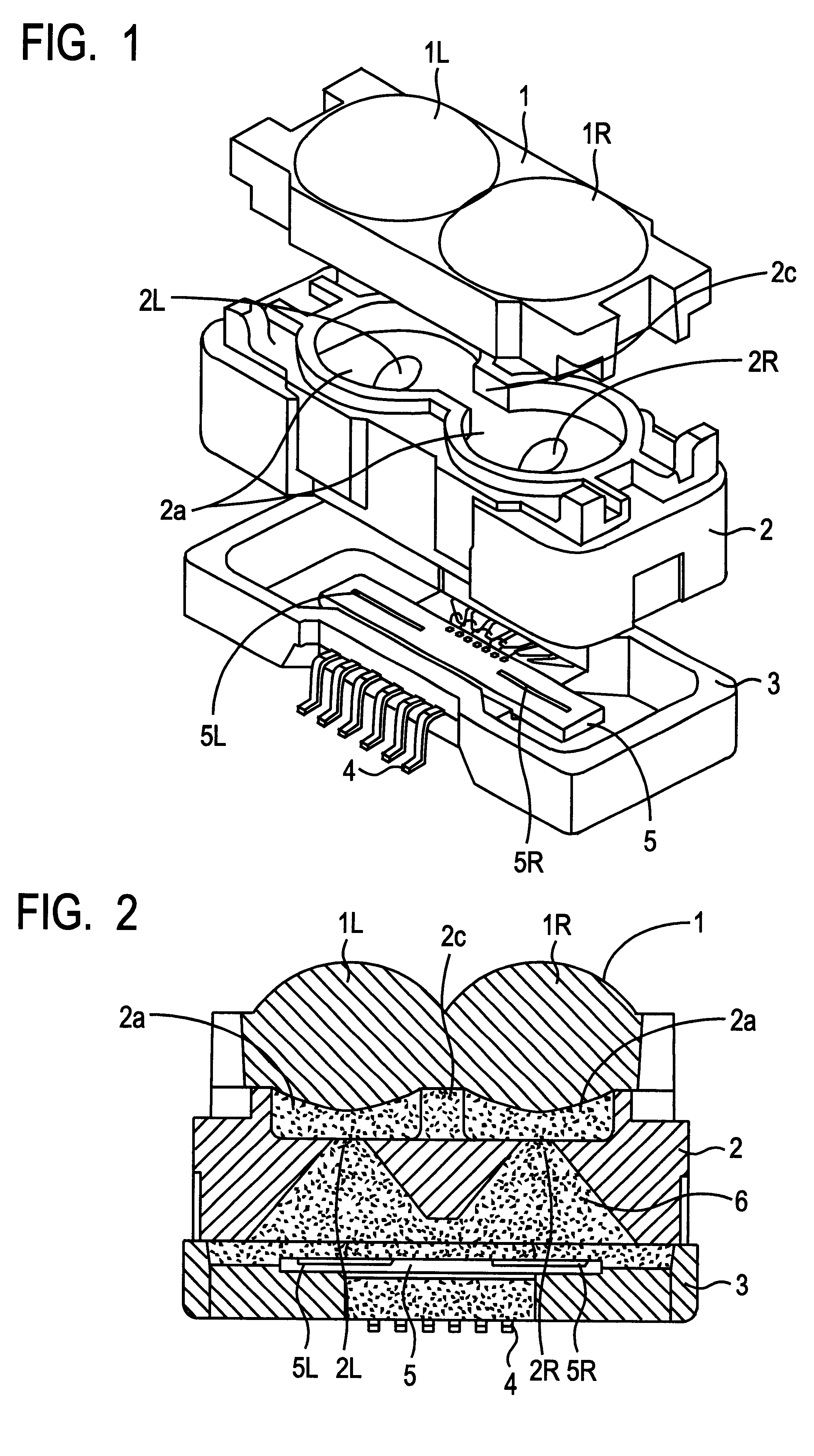
FIG. 1 is an exploded perspective view of a range finder module according to a first embodiment of the invention. FIG. 2 is a cross sectional view of the range finder module of FIG. 1. Referring now to FIGS. 1 and 2, the fundamental configuration of the module is the same with the conventional one shown in FIGS. 6(a) through 8. However, a channel of flow 2c connecting light guide spaces 2a with each other is formed in an aperture mount 2 of the range finder module according to the first embodiment of the invention. The channel of flow 2c is a U-groove formed in a partition wall 2b separating the light guide spaces 2a and facing to an optical lens mount 1. The depth of the U-groove 2c is set such that the bottom of the U-groove 2c is at the level of the openings of the aperture holes 2L and 2R formed from the end face of the aperture mount 2 to the light guide spaces 2a.
For filling the space inside the range finder module, formed by piling up the optical lens mount 1, the aperture mo...
second embodiment
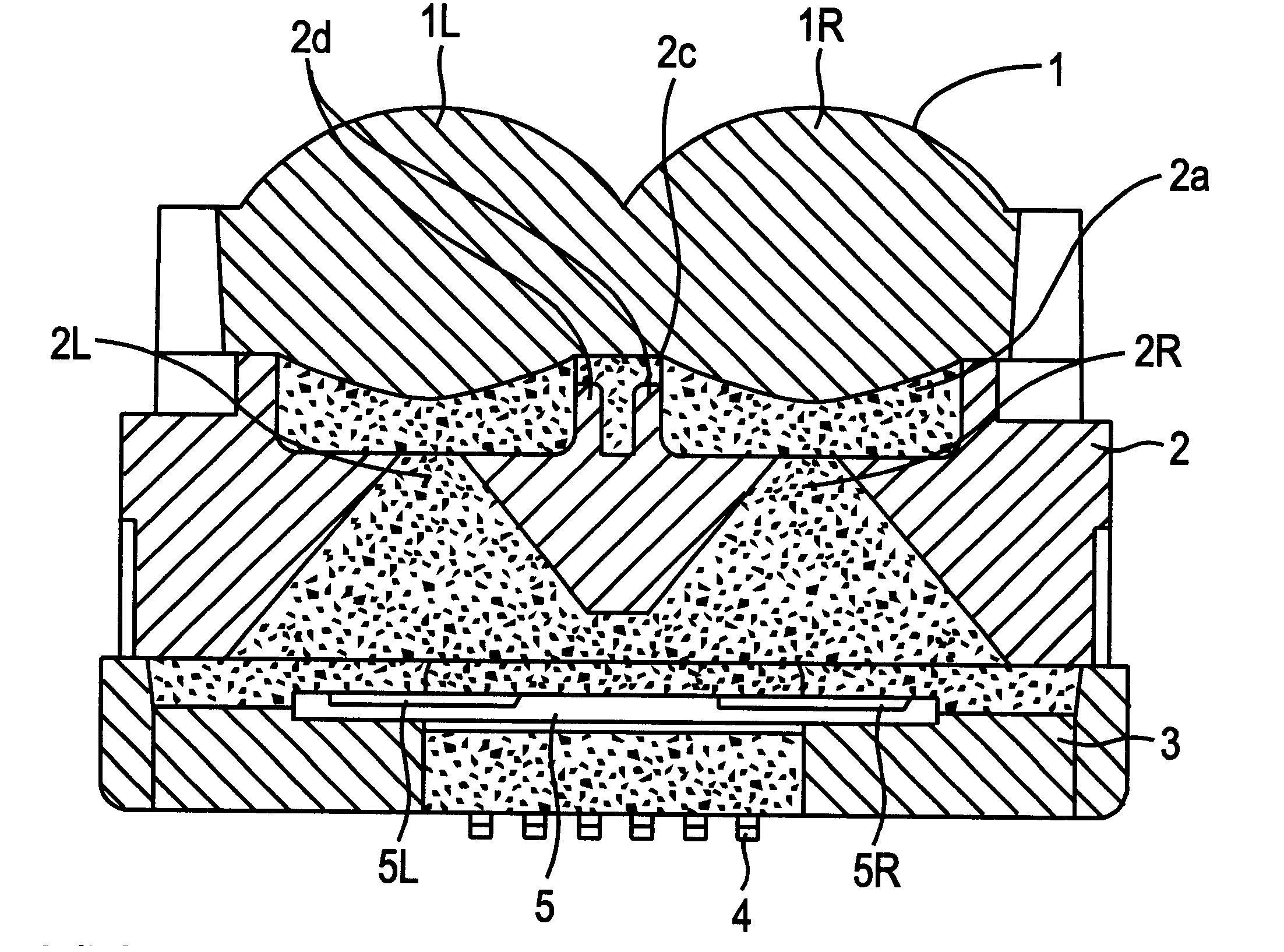
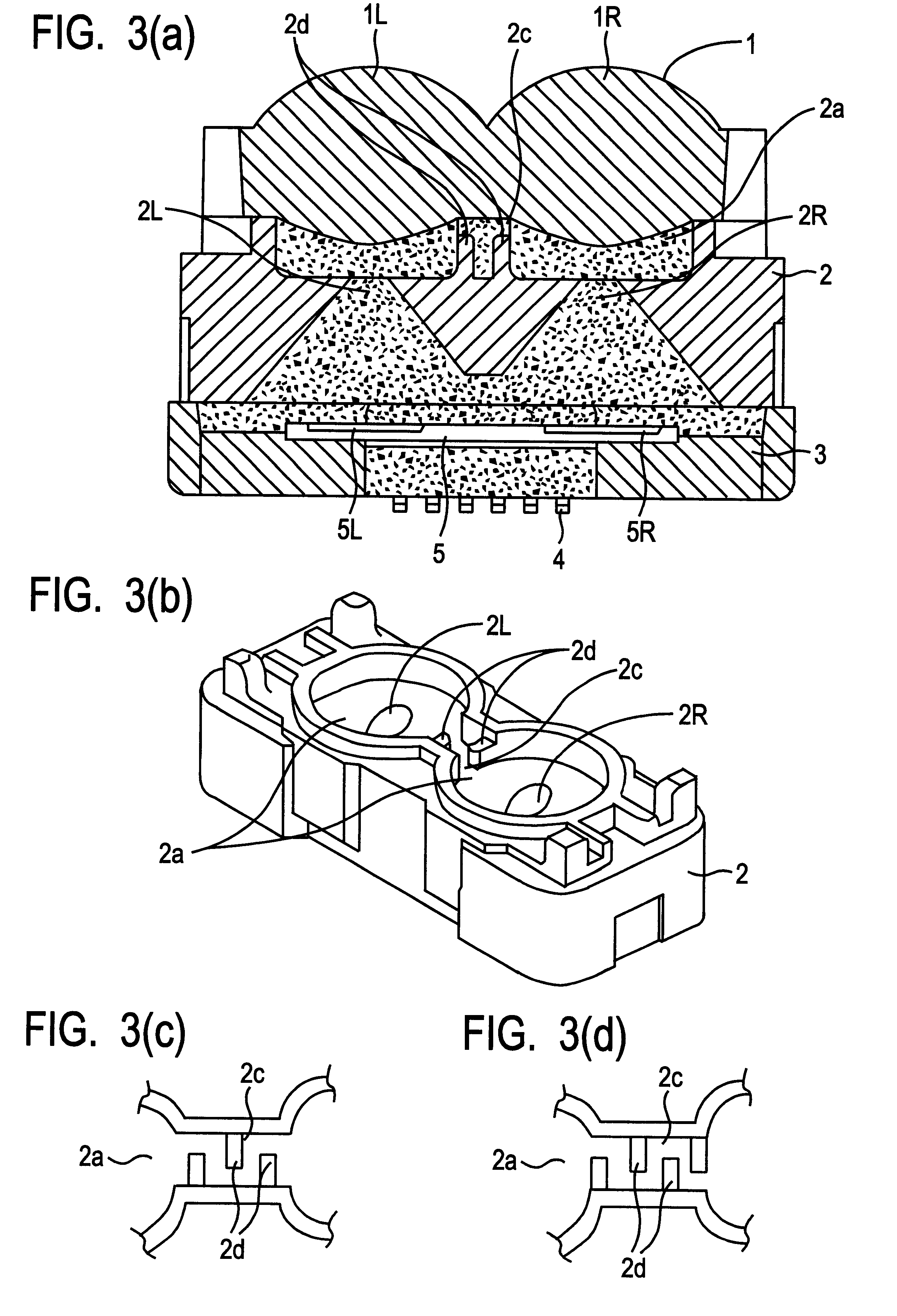
FIG. 3(a) is a cross-sectional view of a range finder module according to a second embodiment of the invention. FIG. 3(b) is a perspective view of the aperture mount of the range finder module of FIG. 3(a). FIG. 3(c) is a cross sectional view showing a modified arrangement of the shield walls different from that shown in FIG. 3(b). FIG. 3(d) is another cross-sectional view showing another modified arrangement of the shield walls different from those shown in FIGS. 3(b) and 3(c). FIG. 4(a) is a cross sectional view showing the incident light paths in the range finder module, that does not include any shield wall. FIG. 4(b) is a cross sectional view showing the incident light paths in the range finder module, that includes shield walls. Referring now to FIGS. 3(a) through 3(d), the range finder module according to the second embodiment further includes shield walls 2d in a U-groove 2c of an aperture mount 2. One shield wall is protruding from one side wall of the U-groove 2c and anoth...
PUM
| Property | Measurement | Unit |
|---|---|---|
| distance | aaaaa | aaaaa |
| transparent | aaaaa | aaaaa |
| module structure | aaaaa | aaaaa |
Abstract
Description
Claims
Application Information