Powder spray-coating cabin

a spray coating and cabin technology, applied in the direction of liquid/solution decomposition chemical coating, solid/suspension decomposition chemical coating, superimposed coating process, etc., can solve problems such as generating disadvantageous air flows

Inactive Publication Date: 2003-07-08
GEMA SWITZERLAND GMBH
View PDF12 Cites 8 Cited by
  • Summary
  • Abstract
  • Description
  • Claims
  • Application Information

AI Technical Summary

Benefits of technology

The invention offers the further substantial advantage that the cabin floor no longer need be a deep funnel and that the system of the evacuation channel below the cabin floor also may be made substantially more shallow and accordingly the cabin sub-structures no longer require an excavated pit and the powder spray-coating cabin can be erected without such a pit while the inside cabin space remains at the same height as in the state of the art.

Problems solved by technology

However corner-subtending cross-sections entail more difficulties in cleaning than do arcuate or circular ones and also may generate disadvantageous air flows.

Method used


Image

  • Powder spray-coating cabin
  • Powder spray-coating cabin
  • Powder spray-coating cabin

Examples


Embodiment Construction

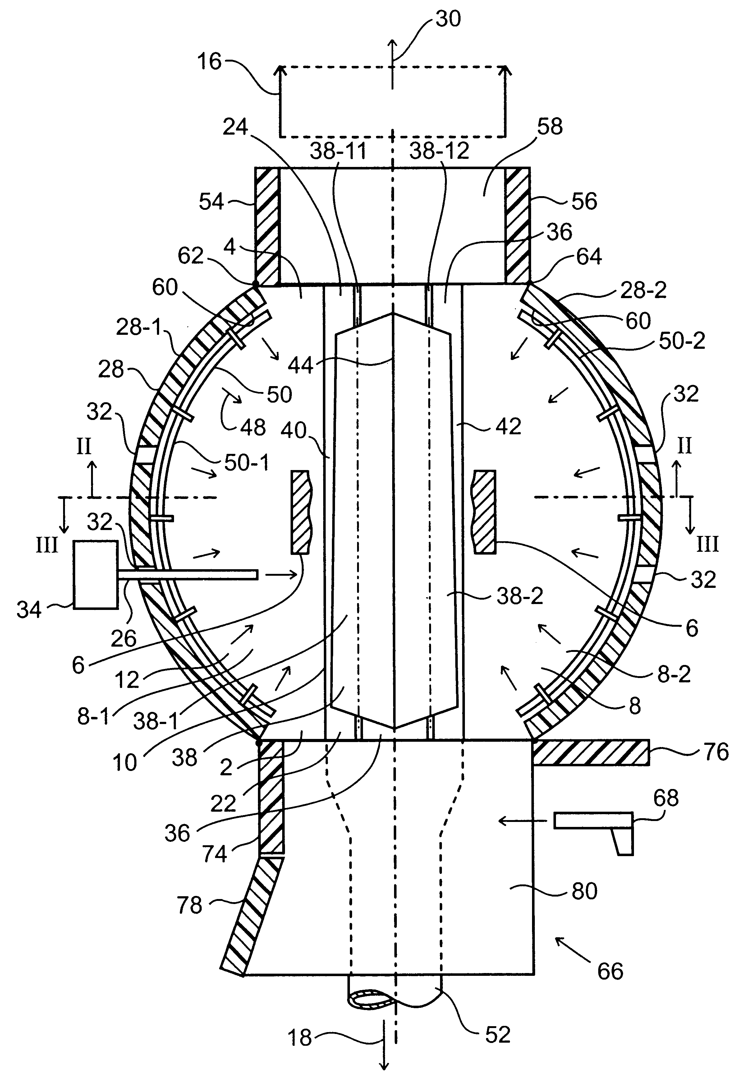
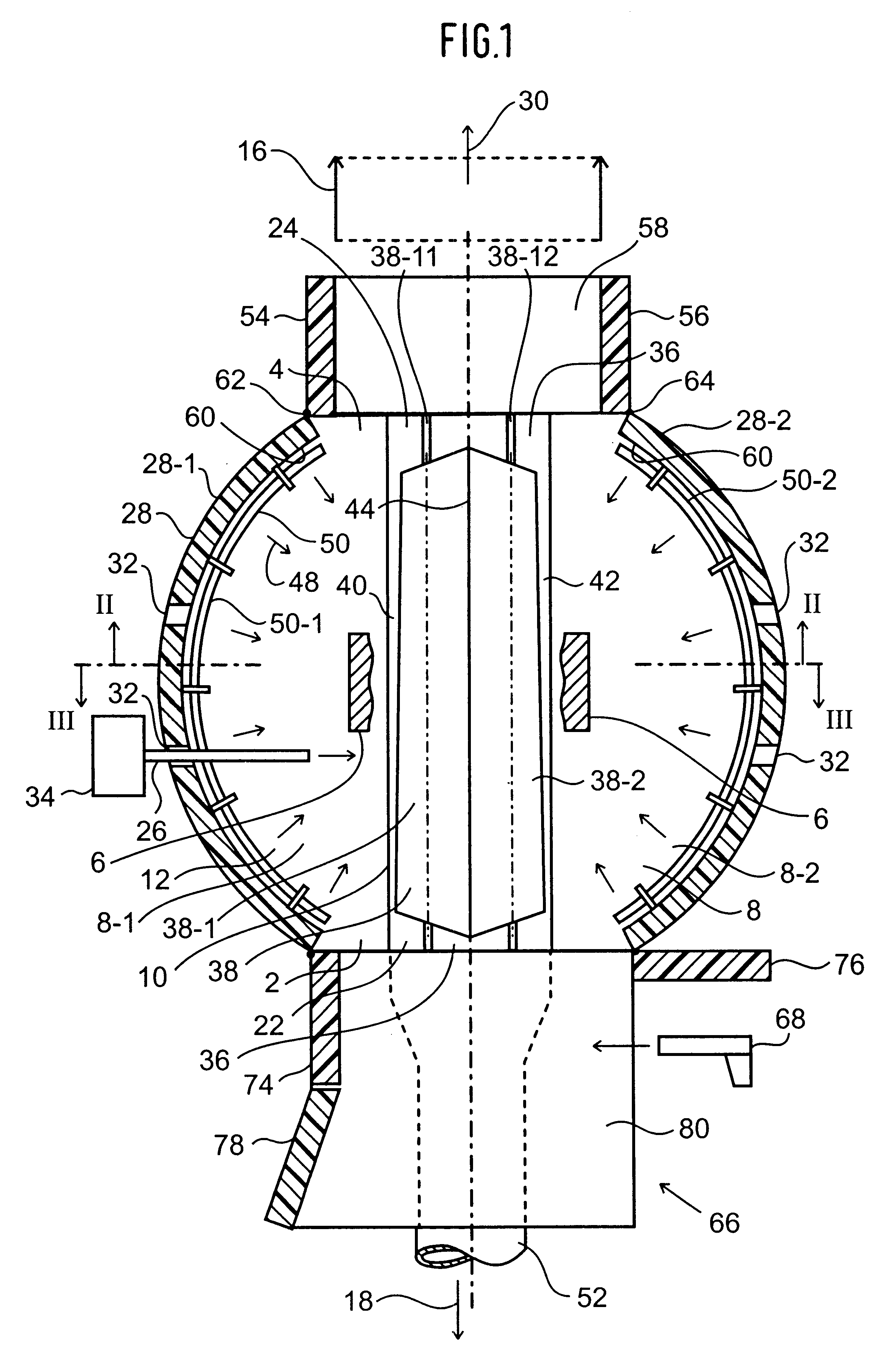
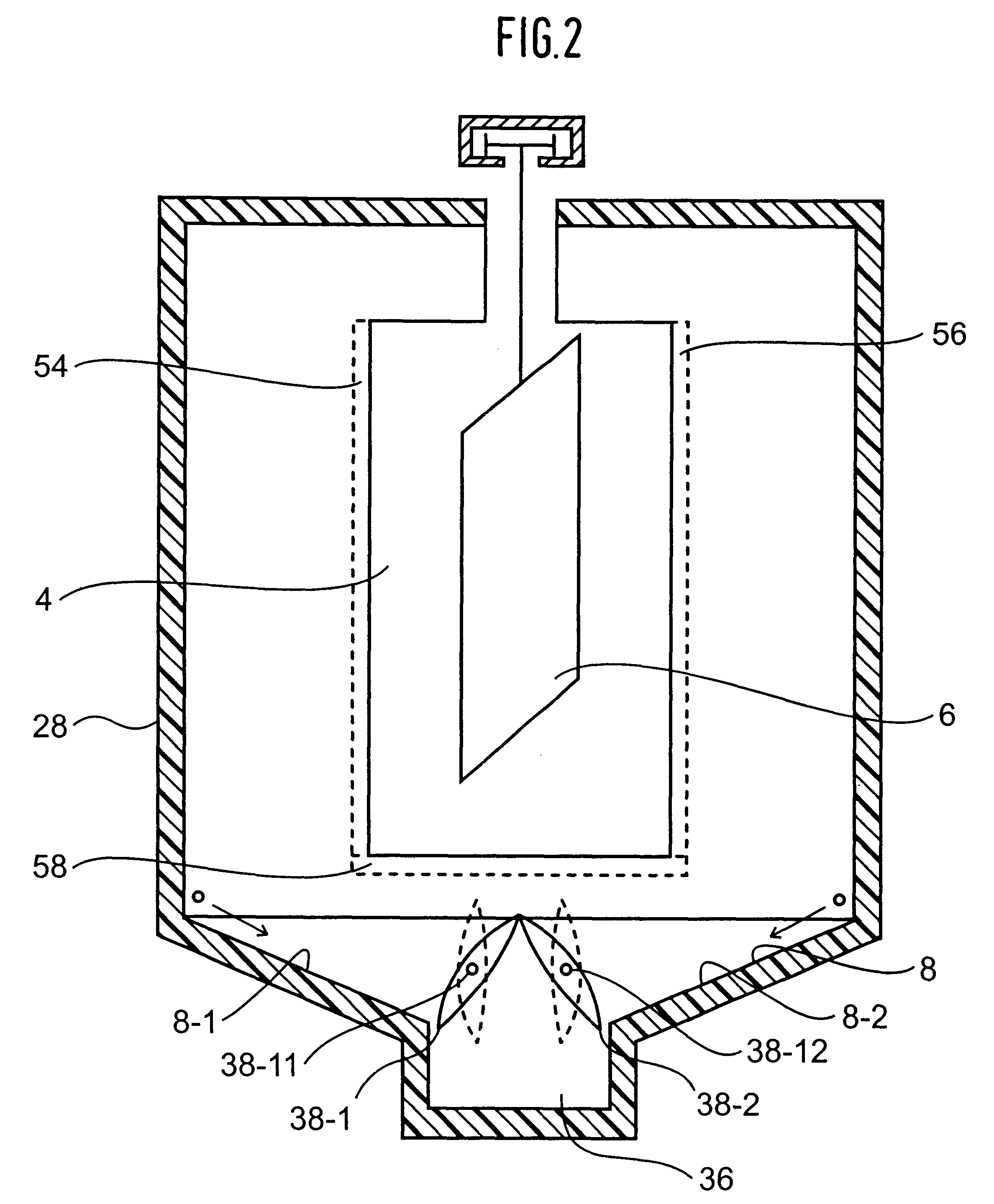
Instead of two suction slots 40 and 42, a single one may be used. This single suction slot may run at the site shown in FIG. 1 or at the center of the suction channel 36 and along its longitudinal direction. The channel cover 38 may consist of fixed elements in lieu of pivoting cover panels. The suction slots 40 and 42 may be plainly eliminated and as a result the entire cabin floor 8 shall be sealed hermetically except for the two suction apertures 22 and 24. Instead of being funnel-shaped or wedge-shaped, the two lateral floor zones 8-1 and 8-2 may also slope outward in gabled manner. In this design appropriately powder suction apertures shall be fitted into the cabin floor 8 along the cabin wall 28 or in this cabin wall. Compressed-air vent holes may be fitted on the roof ridge of such a gabled cabin floor 8 through which the compressed air may drive powder deposited on the cabin floor toward the suction apertures.

Presumably for the same reasons that water draining into a pipe, f...


PUM

PropertyMeasurementUnit
pressureaaaaaaaaaa
concentrationsaaaaaaaaaa
heightaaaaaaaaaa

Abstract

A powder spray-coating cabin, in particular a vertically cylindrical cabin, has its air suction flows shifted away from the center of spray coating toward object wall passages.

Description

1. Field of the InventionThe invention relates to a powder spray-coating cabin. More particularly, the present invention relates to a powder spray-coating cabin fitted with two mutually opposite object wall-passages used in the transportation of objects to be coated through the cabin and with a suction channeling system configured at a lower end of an inside cabin space used to aspirate air and excess powder out of the inside cabin space.2. Description of the Related ArtA powder spray-coating cabin of this kind is known from EP 0 839 583 A2. It may be a vertically cylindrical cabin fitted with a funnelling floor and communicating at the cabin center through a vacuum hookup with an external suction source. A similar cylindrical powder spray-coating cabin is known from DE 195 00 782 A1. In addition to the cabin floor in the form of an evacuation funnel, this latter design also includes a gutter-like floor rim along the cabin wall allowing evacuating, besides the flow from the said fun...

Claims


Application Information

Patent Timeline
Patent Type & Authority Patents(United States)
IPC IPC(8): B05B15/12B05B14/48B05B16/25B05B16/40B05B16/60
CPCB05B15/1211B05B15/1218B05B15/1222B05B15/1229B05B16/60B05B16/405B05B14/48B05B16/25Y02P70/10
Inventor GELAIN, SILVANO
Owner GEMA SWITZERLAND GMBH
Why Eureka
Try Eureka