
Fixed supported structure of crystal ball transmission

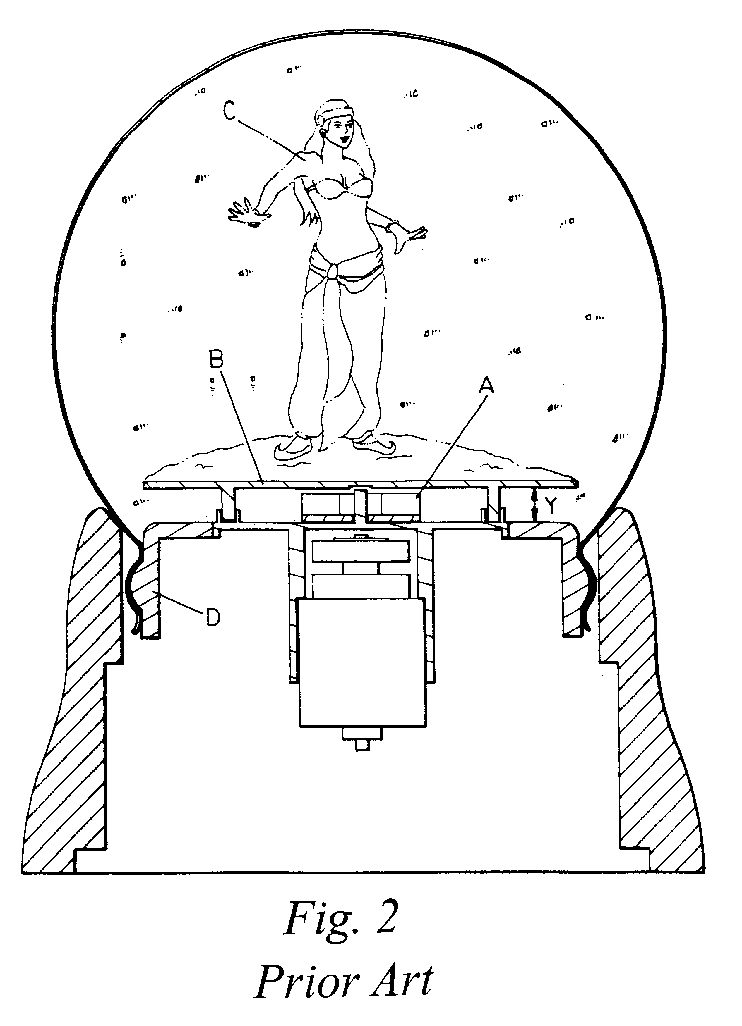
a technology of supporting structure and crystal ball, which is applied in the direction of display means, instruments, advertising, etc., can solve the problems of affecting the smooth passage of suspended substances, the design of rotating vanes will be limited, and the exposed outside of rotating vanes not being propitious to total beauty

Inactive Publication Date: 2003-07-15
LIU JACK
View PDF5 Cites 14 Cited by
  • Summary
  • Abstract
  • Description
  • Claims
  • Application Information

AI Technical Summary

Benefits of technology

The further object of the invention is to provide a fixed supporting structure of crystal ball transmission characterized in that by means of pushing upward a cup-shaped supporting body and stopping at the buffer body so as to form supporting effect. When heat expansion and cold contraction due to temperature difference causes the deformation of rubber sealed-spigot, the horizontal position of the fixed disc of decoration can be kept unchanged, so as to ensure the decoration not to incline, and after suspended substance disturbed to maintain the flowing out-in passage being smooth.

Problems solved by technology

It is no doubt that the design of the rotating vane will be limited.
In addition, the rotating vane exposed outside is not propitious to the total beauty.
It seriously affects the smoothness of passage for suspended substance.

Method used


Image

  • Fixed supported structure of crystal ball transmission
  • Fixed supported structure of crystal ball transmission
  • Fixed supported structure of crystal ball transmission

Examples


Embodiment Construction

The embodiment of the invention will be described below in conjunction with the drawings; the structural feature, function and object could be further understood with the help of the following figures and description.

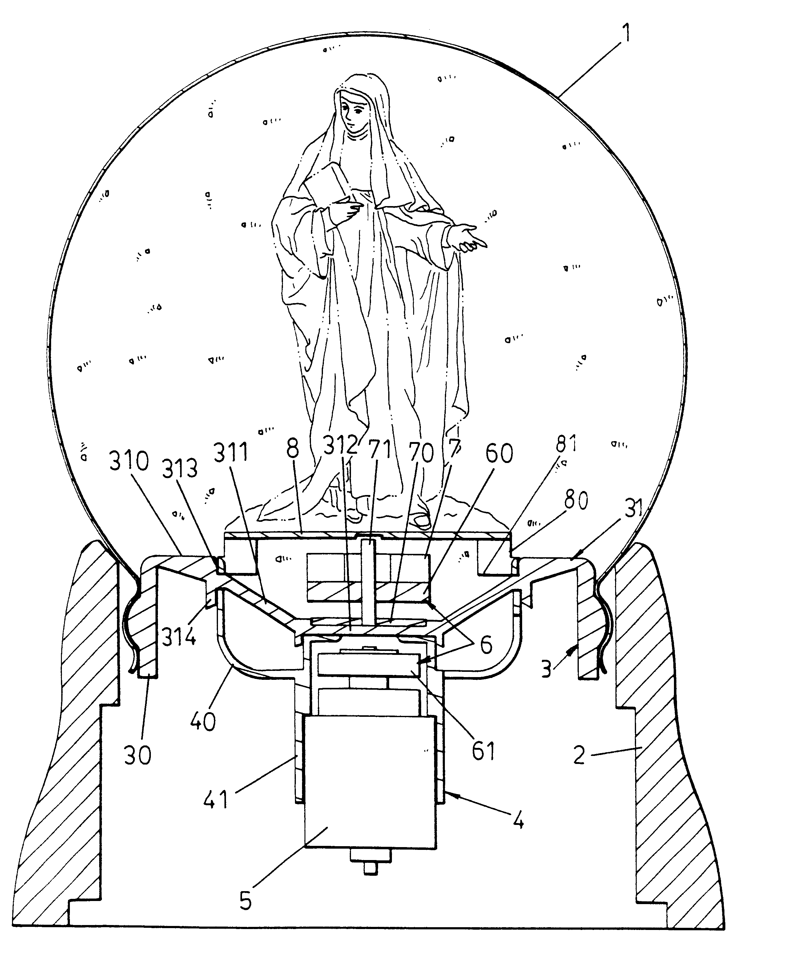
See the section view of the invention shown in FIG. 4, the invention comprises crystal ball 1, base 2, soft rubber sealed-spigot 3, fixed seat 4 and driven motor 5, magnet set 6, disturbing vane 7, and fixed disc 8 of decoration and so on installed on above rubber sealed-spigot 3 and fixed seat 4.

Wherein, crystal ball 1 at its opening is sheathed in the top end of the base 2. Then, fill said crystal ball with liquid; finally, press said rubber sealed-spigot to plug into the opening of said crystal ball for sealing so as to ensure no leakage of liquid,

As shown in the figure, the above rubber sealed-spigot 3 comprises circular sealed-spigot body 30 used for sealing the opening of the crystal ball and disc-shaped elastic buffer body 31. Wherein, the buffer body 31 further ...


PUM


Abstract

The invention relates to a fixed supporting structure of a crystal ball transmission, comprising a crystal ball, a base, a soft rubber sealed-spigot, a fixed seat and a driven motor, a magnet set, disturbing vane and a fixed disc of decoration and so on installed on above rubber sealed-spigot and fixed seat; characterized in that the rubber sealed-spigot is designed to have a circular sealed-spigot body for sealing the crystal ball opening and a disk-shaped elastic buffer body, wherein, the buffer body further comprises an upper section planar disc edge, a middle section inclined disc edge and a lower section planar disc bottom; and by means of pushing upward a cup-shaped supporting body of the fixed seat and stopping at the buffer body so as to form selected point supporting; when heat expansion and cold contraction are happened due to temperature difference of liquid within the crystal ball, the middle section inclined disc edge of the buffer body will stretch elastically and automatically to absorb the change of volume, by using the upward supporting force of the cup-shaped supporting body under the buffer body to ensure the horizontal position of the fixed disc of decoration unchanged, so as to further ensure the decoration does not incline for buffer body deformation due to the change of liquid volume and to maintain the flowing out-in passage of suspended substance being smooth.

Description

The invention relates generally to a fixed supporting structure of a crystal ball transmission, comprising a crystal ball, a base, a soft rubber sealed-spigot, a fixed seat and a driven motor, a magnet set, disturbing vane and a fixed disc of decoration and so on installed on above rubber sealed-spigot and fixed seat; characterized in that the rubber sealed-spigot is designed to have a circular sealed-spigot body and a disk-shaped elastic buffer body for sealing the crystal ball opening, wherein, the buffer body further comprises an upper section planar disc edge, a middle section inclined disc edge and a lower section planar disc bottom; and by means of pushing upward the cup-shaped supporting body of the fixed seat and stopping at the buffer body so as to form selected point supporting; when heat expansion and cold contraction are happened due to temperature difference of liquid within the crystal ball, the middle section inclined disc edge of the buffer body will stretch elastica...

Claims


Application Information

Patent Timeline
Patent Type & Authority Patents(United States)
IPC IPC(8): G09F19/08G09F19/00
CPCG09F19/08
Inventor LIU, JACK
Owner LIU JACK
Learn More