
Sensor validation apparatus and method

a technology of sensor validation and apparatus, which is applied in the direction of instruments, coding, nuclear elements, etc., can solve the problems of high initial cost and high maintenance cost of hardware continuous emission monitoring systems (cems), and achieve the effect of reducing the initial cost and high maintenance cos

Inactive Publication Date: 2003-07-15
ASPENTECH CORP
View PDF17 Cites 138 Cited by
  • Summary
  • Abstract
  • Description
  • Claims
  • Application Information

AI Technical Summary

Problems solved by technology

If the sensors are faulty, the optimized target values are not valid.
Hardware continuous emissions monitoring systems (CEMS) have both a high initial cost and a high maintenance cost.
However the breaking of this correlation structure could also be due to process upset, process transition, or some other reason unrelated to sensor fault.
The sensor validation technology uses a sub-optimal reconstruction procedure for identification, does not address classification, and makes use of an "encoder" neural network which is a non-linear version of PCA.

Method used


Image

  • Sensor validation apparatus and method
  • Sensor validation apparatus and method
  • Sensor validation apparatus and method

Examples


Embodiment Construction

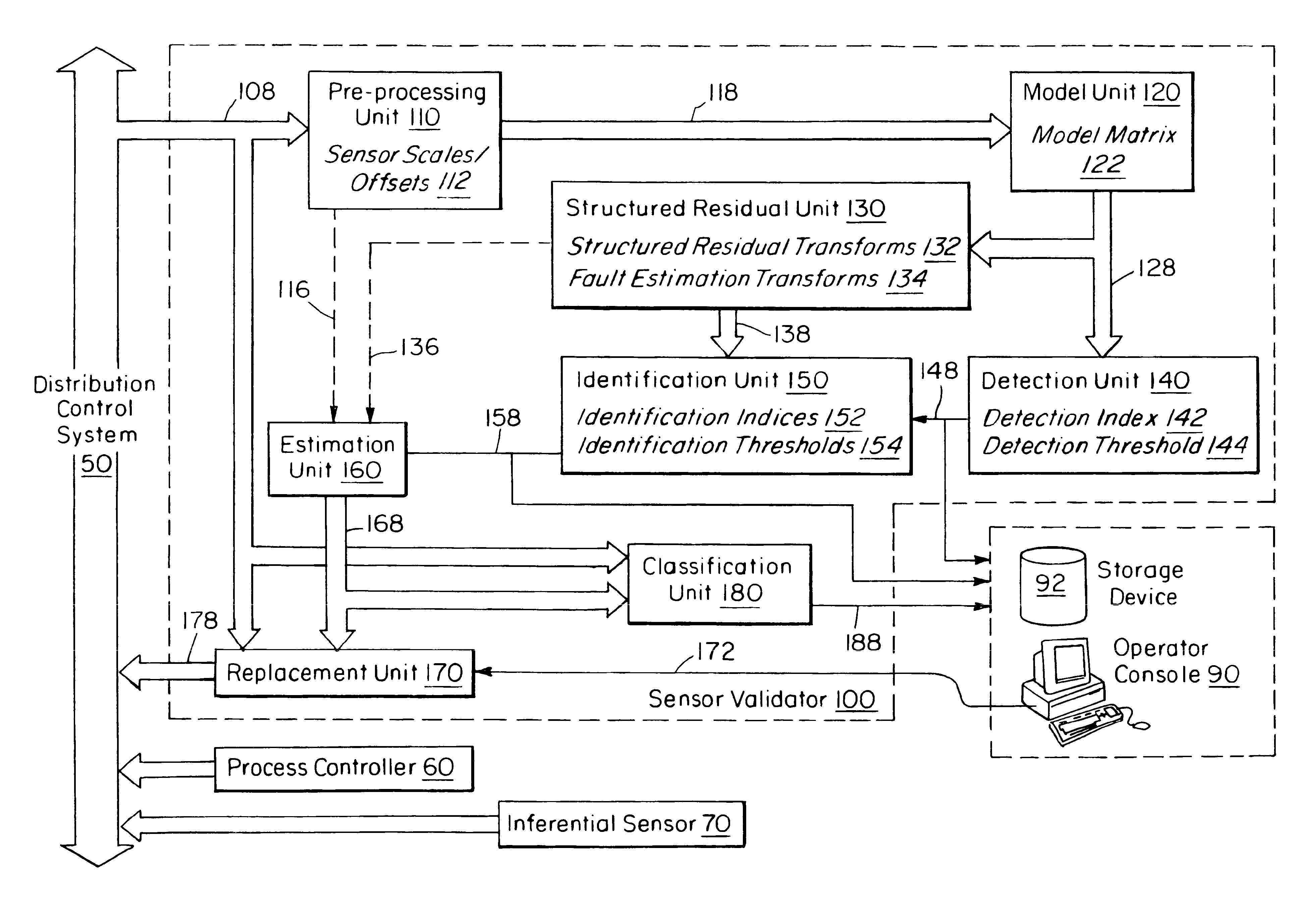
The sensor validation apparatus 100 of this invention is shown in FIG. 11. The external input to the sensor validator consists of sensor measurements 108, which may include status information, as might be available, for example, from a Distributed Control System (DCS) 50 in a manufacturing plant. The purpose of the invention is to use redundant information in the sensor measurements to detect when a sensor has failed, and, optionally, to provide a replacement value for a failed sensor. Other devices such as a process controller 60 or inferential sensor 70 that make use of the sensor measurements can then use the replacement values if necessary. This allows these devices to continue operation in the presence of failed sensors.

Referring again to FIG. 11, the sensor validator 100 consists of eight computational units that implement the various phases of sensor validation. These computational units, which may be implemented using a microprocessor or any other desired type of computer, a...


PUM


Abstract

An apparatus and method is disclosed for detecting, identifying, and classifying faults occurring in sensors measuring a process. A variety of process models can be used such as first principles models, dynamic multivariable predictive control models, from data using statistical methods such as partial least squares (PLS) or principal component analysis. If faults are identified in one or more sensors, the apparatus and method provide replacement values for the faulty sensors so that any process controllers and process monitoring systems that use these sensors can remain in operation during the fault period. The identification of faulty sensors is achieved through the use of a set of structured residual transforms that are uniquely designed to be insensitive to specific subsets of sensors, while being maximally sensitive to sensors not in the subset. Identified faults are classified into one of the types Complete Failure, Bias, Drift, Precision Loss, or Unknown.

Description

I FIELD OF THE INVENTIONThe present invention pertains, in general, to process controllers and process monitoring systems that make use of sensors for measuring process variables. In particular it relates to a system that detects and identifies one or more sensor faults, classifies the types of sensor fault, and replaces erroneous sensor values with estimates of the correct process variable values.II BACKGROUND OF THE INVENTIONSensor validation is an important step for many model based applications in the process industries. Typical model based applications include model predictive control applications (MPC), and inferential sensing applications in which costly or infrequent measurements, available from laboratory samples or hardware analyzers, are replaced by regularly available inferred values from the model.In a typical MPC application, steady state optimization is performed to find the optimal target values for the controlled and manipulated variables. If the sensors are faulty,...

Claims


Application Information

Patent Timeline
Patent Type & Authority Patents(United States)
IPC IPC(8): G05B9/02
CPCG05B9/02
Inventor QIN, S. JOEGUIVER, JOHN P.
Owner ASPENTECH CORP
Learn More