
Method for demodulating signal

a signal and modulation technology, applied in the field of methods and apparatuses for demodulating signals, can solve the problems of inability to transfer information symbols to be transmitted, power consumption of terminals, time-varying phase jitter of signals to be transmitted, etc., to achieve simple terminal structure, simple structure of central station, and modulation index variation

Inactive Publication Date: 2003-07-22
NOKIA SOLUTIONS & NETWORKS OY
View PDF1 Cites 2 Cited by
  • Summary
  • Abstract
  • Description
  • Claims
  • Application Information

AI Technical Summary

Benefits of technology

In the preferred embodiments of the invention the modulation index variation can be compensated in the receiver. Thus, a simple FM modulator can be used as the transmitter. This provides significant advantages in several telecommunication systems, for example in point-to-multipoint (PMP) systems that include one central station and a large number of terminals. The structure of the central station may be complex, but the simple structure of the terminals provides significant savings. The present invention makes this possible.

Problems solved by technology

Information symbols to be transferred cannot be transferred as such over the transmission path owing to the losses occurring on the transmission path and to the capacity of the transmission path.
This is substantial particularly in view of the power consumption of the terminals.
However, keeping the modulation index constant during transmission constitutes a problem for a wider use of the FM modulator.
When using the FM modulator the variation of the modulation index causes time varying phase jitter to the signal to be transmitted.
Since the phase of a generated TFM signal cannot be kept at a desired level during transmission, the performance deteriorates significantly in a coherent receiver.
A drawback with this system is that the structure of the transmitter becomes complicated.
These are demanding tasks and the latter requires the existence of known data, such as a training sequence.
However, if the deviation of the modulation index between the receiver and the transmitter is high, then a mere phase synchronization algorithm is not enough.

Method used


Image

  • Method for demodulating signal
  • Method for demodulating signal
  • Method for demodulating signal

Examples


Embodiment Construction

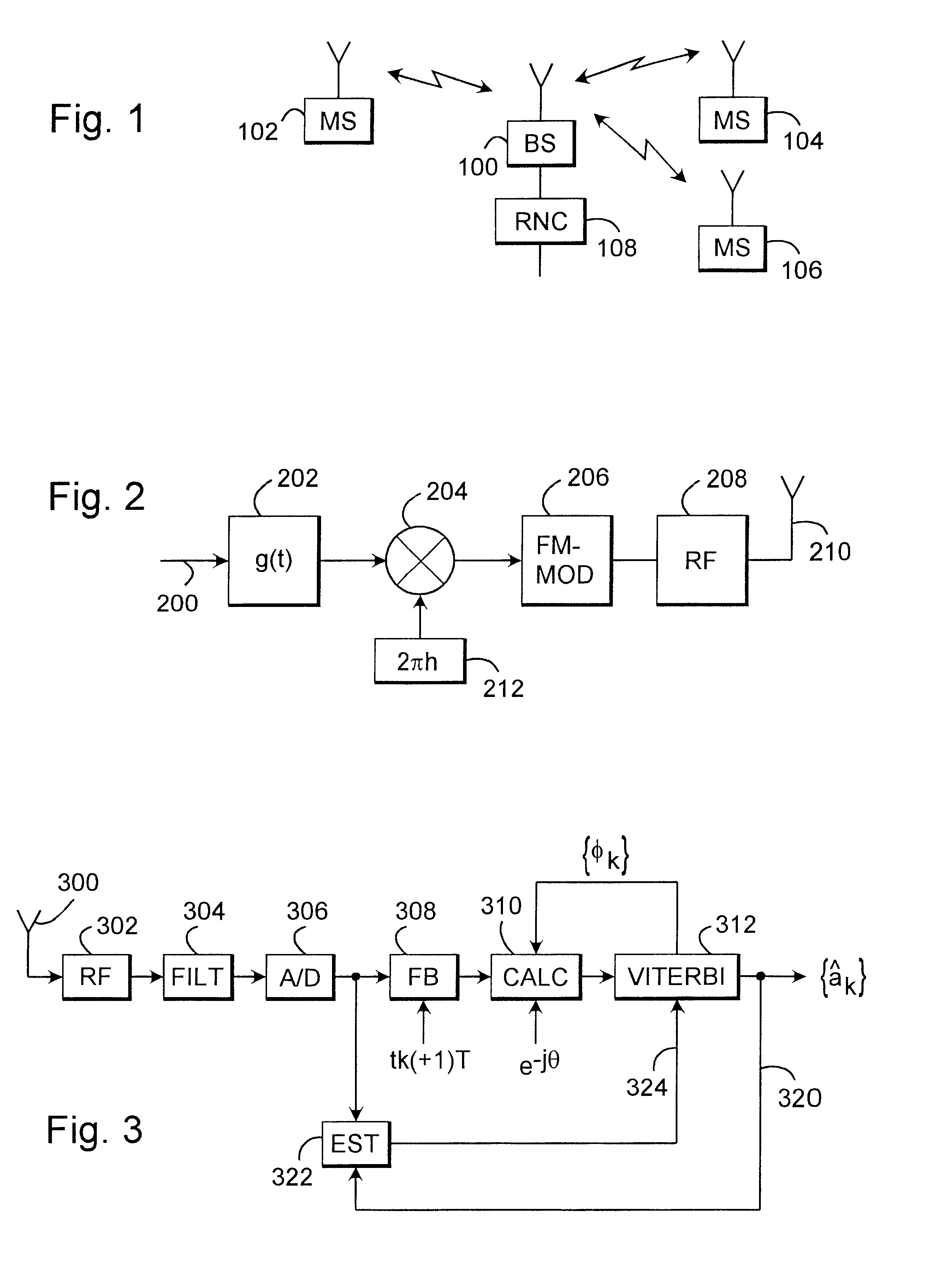
FIG. 1 is a simplified illustration of a digital data transmission system, in which the solution of the invention can be applied. What is concerned here is a part of a cellular radio system comprising a base station 100 with a radio connection to subscriber terminals 102 to 106, which may be fixedly mounted, vehicle mounted or hand-held portable terminals. The base station 100 communicates further with a base station controller 108, which conveys the connections of the terminals elsewhere in the network. The base station controller 108 controls the base station communicating therewith in a centralized manner. A connection can also be maintained from the-cellular radio system to the public switched telephone network through the base station controller.

The subscriber terminals are small transceivers, and the base station generally comprises a set of transceivers, each one of which communicating with a subscriber terminal under the control of the base station controller.

FIG. 1 also ill...


PUM


Abstract

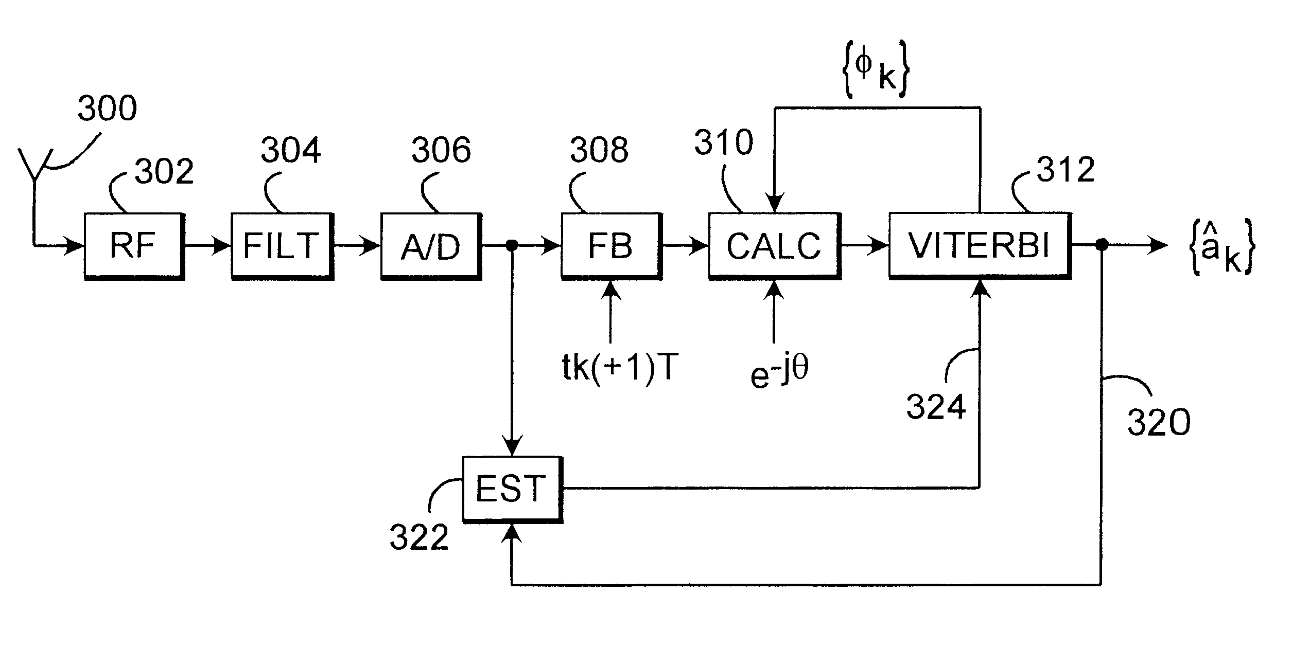
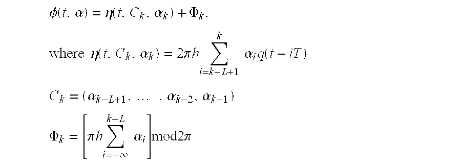
The invention relates to a demodulator and a demodulation method for a TFM-modulated signal comprising symbols, the method comprising the steps of calculating an estimate for the symbols, determining an estimate for the phase shift, determining a modulation index estimate error using the phase shift and the symbol estimates and removing the estimated error from the modulation index estimate using the symbol estimates.

Description

FIELDThe invention relates to a method and an apparatus for demodulating a TFM-modulated signal comprising symbols. The invention is particularly applicable in radio systems that employ the TFM modulation method.A modulation method to be used on the transmission path is an essential parameter in data transmission systems, particularly in radio systems. Information symbols to be transferred cannot be transferred as such over the transmission path owing to the losses occurring on the transmission path and to the capacity of the transmission path. Instead the symbols must be modulated using an appropriate method in order to obtain an adequate capacity and quality on the transmission path.Particularly in radio systems an essential factor is the band-width required by the transmission. It is an aim to achieve a transmission capacity that is as extensive as possible on a limited bandwidth. On the other hand, both the transmitter and the receiver should be as simple as possible and advanta...

Claims


Application Information

Patent Timeline
Patent Type & Authority Patents(United States)
IPC IPC(8): H04L27/14
CPCH04L27/14
Inventor KIVIRANTA, MARKKU
Owner NOKIA SOLUTIONS & NETWORKS OY
Learn More