Alignment guide assembly for spinal stabilization

a spinal stabilization and alignment guide technology, applied in the field of spinal stabilization surgical procedures, can solve the problems of misalignment of the vertebrae, pain and disability of a large segment of the population, and bore which does not equalize the length of both vertebra

Inactive Publication Date: 2003-07-29
ZIMMER SPINE INC
View PDF34 Cites 106 Cited by
  • Summary
  • Abstract
  • Description
  • Claims
  • Application Information

AI Technical Summary

Problems solved by technology

Chronic back problems cause pain and disability for a large segment of the population.
I have found that in such a procedure, the forming of the bores can cause misalignme

Method used


Image

  • Alignment guide assembly for spinal stabilization
  • Alignment guide assembly for spinal stabilization
  • Alignment guide assembly for spinal stabilization

Examples


Embodiment Construction

1. Generally

Referring now to the several drawing figures in which identical elements are numbered identically throughout, a description of the preferred embodiment will now be provided. For purposes of illustrating a preferred embodiment, a description of the surgical procedure will be given with respect to an implant 10 such as that shown and described in commonly assigned and co-pending U.S. patent application Ser. No. 07 / 702,351. It will be appreciated that the present surgical procedure can apply to a wide variety of implants including threaded implants such as those shown in the aforementioned U.S. Pat. Nos. 5,015,247 and 4,961,740 as well as non-threaded implants such as shown in U.S. Pat. No. 4,507,269 or other implants. The term "implant" as used herein may also include bone implants (e.g., autograft, allograft or artificial bone).

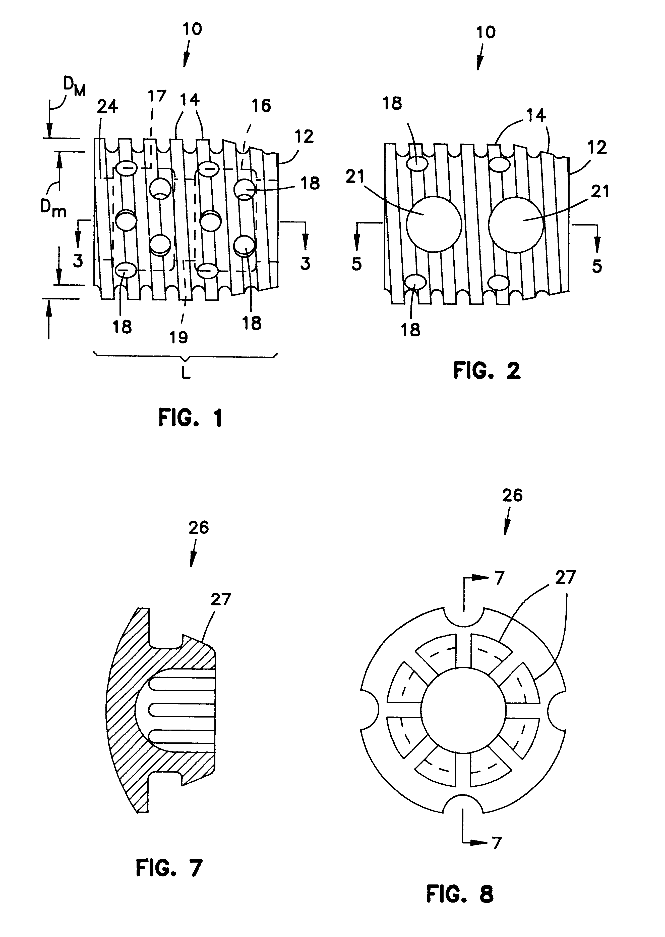
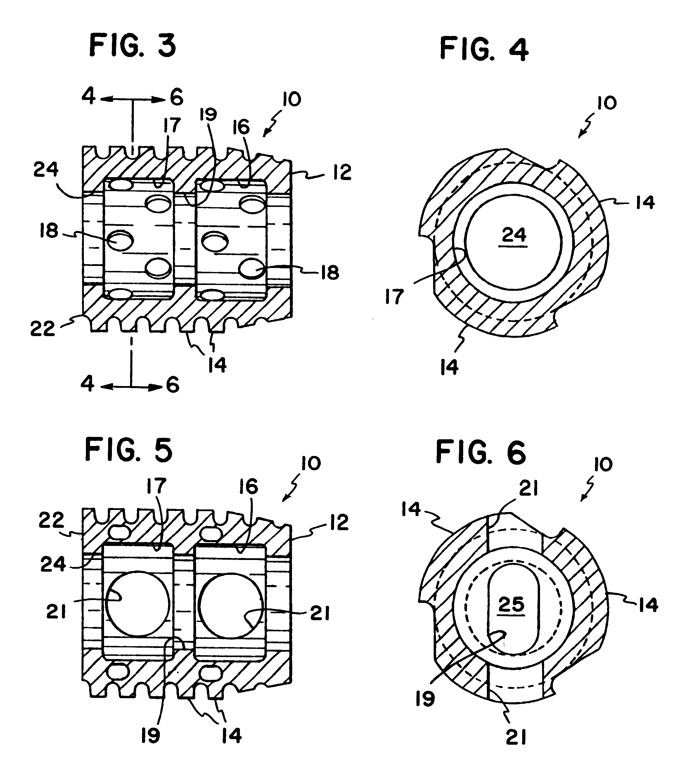
The implant 10 (FIGS. 1-6) is a hollow cylinder 12 having male threads 14 exposed on the exterior cylindrical surface of cylinder 12. The cylinder...


PUM


Abstract

An alignment guide for placing an intervertebral spinal implant into a disc space includes a body and a pair of parallel pins spaced at a predetermined distance from one another. The body may be x-ray transparent while the pins are made of material that is visible to x-ray, allowing the guide assembly to imaged in the spine using x-ray.

Description

I. BACKGROUND OF THE INVENTION1. Field of the InventionThis invention pertains to a spinal stabilization surgical procedure. More particularly, this invention pertains to a method for implanting a fusion spinal implant between two vertebrae.2. Description of the Prior ArtChronic back problems cause pain and disability for a large segment of the population. In many cases, the chronic back problems are attributed to relative movement between vertebrae in the spine.Orthopaedic surgery includes procedures to stabilize vertebrae. Common stabilization techniques include fusing the vertebrae together.Fusion techniques include removing disc material which separates the vertebrae and impacting bone into the disc area. The impacted bone fuses with the bone material of the vertebrae to thereby fuse the two vertebrae together.As in any surgical technique, it is desirable in back surgery to provide a procedure which permits rapid post-operative recovery. To this end and to increase the probabili...

Claims


Application Information

Patent Timeline
IPC IPC(8): A61B17/16A61B17/17A61F2/30A61F2/44A61F2/46A61B17/86A61B17/68A61F2/28A61F2/00A61B17/02A61B17/56A61B17/90
CPCA61B17/1757A61F2/30744A61F2/446A61F2/4611A61B17/86A61B2017/0256A61F2/30723A61F2/442A61F2/4455A61F2002/2835A61F2002/30235A61F2002/305A61F2002/30672A61F2002/30785A61F2002/30787A61F2002/3085A61F2002/30861A61F2002/30868A61F2002/4475A61F2002/448A61F2002/464A61F2002/4681A61F2220/0025A61F2230/0069A61F2/4637A61F2002/30593
Inventor KUSLICH, STEPHEN D.KOHRS, DOUGLAS W.
Owner ZIMMER SPINE INC
Why Eureka
Try Eureka