
Roller type test stand for testing motor vehicles and/or tires

Inactive Publication Date: 2003-08-05
RENK AG
View PDF3 Cites 6 Cited by
  • Summary
  • Abstract
  • Description
  • Claims
  • Application Information

AI Technical Summary

Benefits of technology

This configuration ensures all forces and losses are accurately measured, reducing measurement errors and allowing for adaptable testing across various vehicle categories without external disturbances, and eliminates the need for expensive pressurized oil lubrication.

Problems solved by technology

Such disturbances can be caused, for example, by a lubricant supply device arranged outside the roller type test stand and connected via supply lines to the drive and the bearings.

Method used


Image

  • Roller type test stand for testing motor vehicles and/or tires
  • Roller type test stand for testing motor vehicles and/or tires
  • Roller type test stand for testing motor vehicles and/or tires

Examples


Embodiment Construction

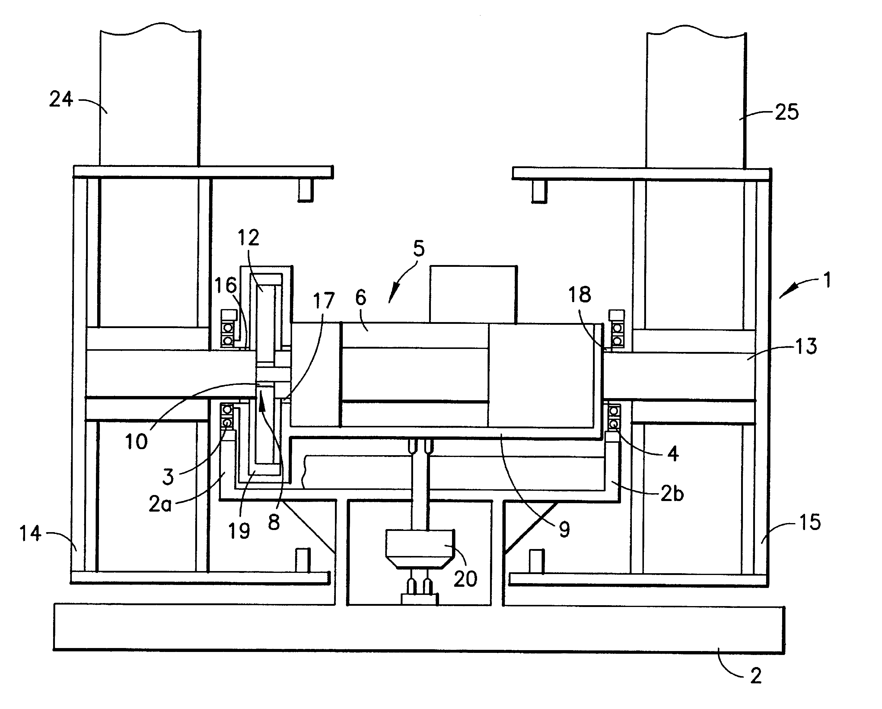
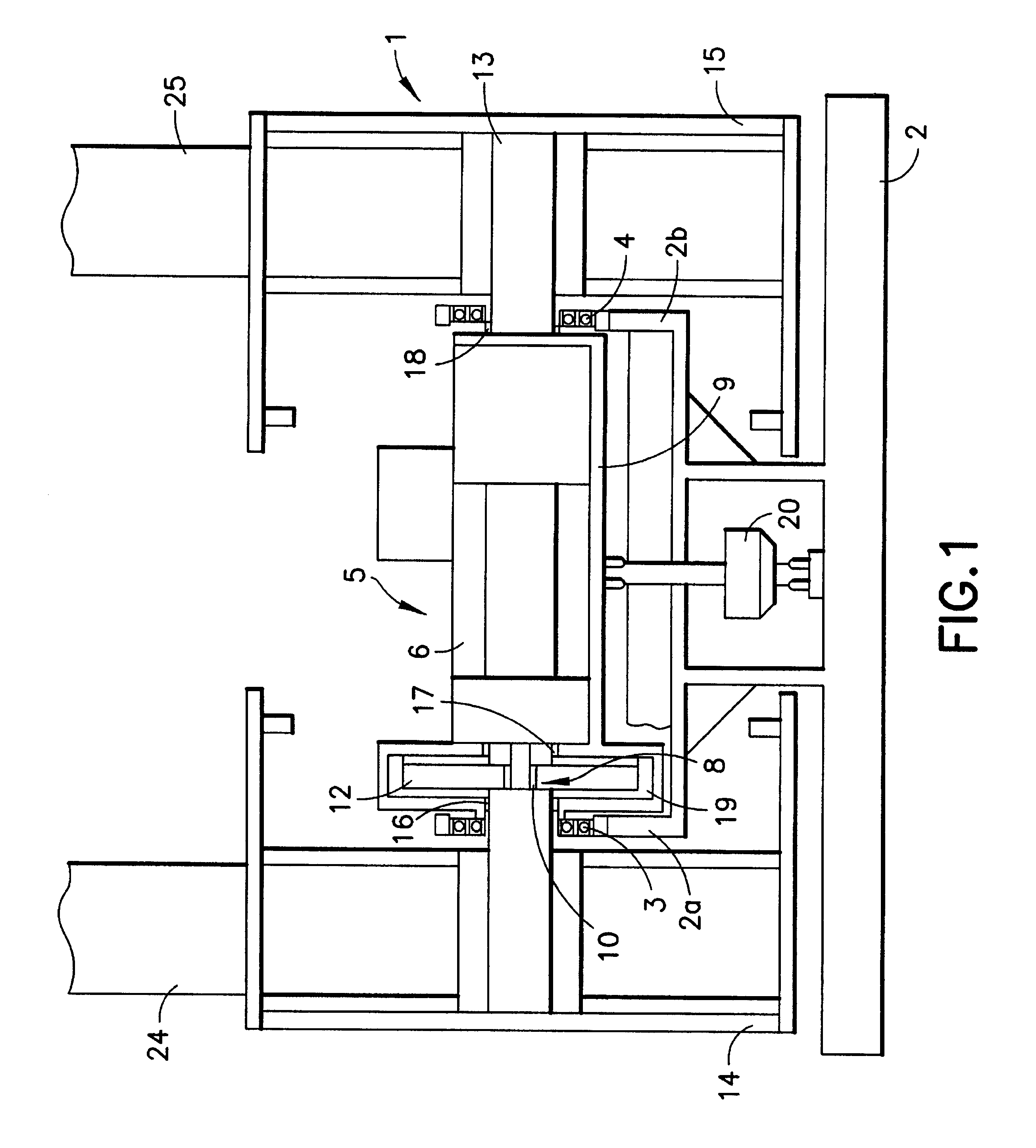
Referring now to FIG. 1 a side view of a roller type test stand 1 according to the present invention is shown. The roller type test stand 1 comprises a supporting frame 2 and supporting arms 2a, 2b arranged thereon. A motor / transmission combination 5 is mounted in a pivotable frame 9 which is pivotably mounted between the supporting arms 2a, 2b by bearing elements 3, 4.

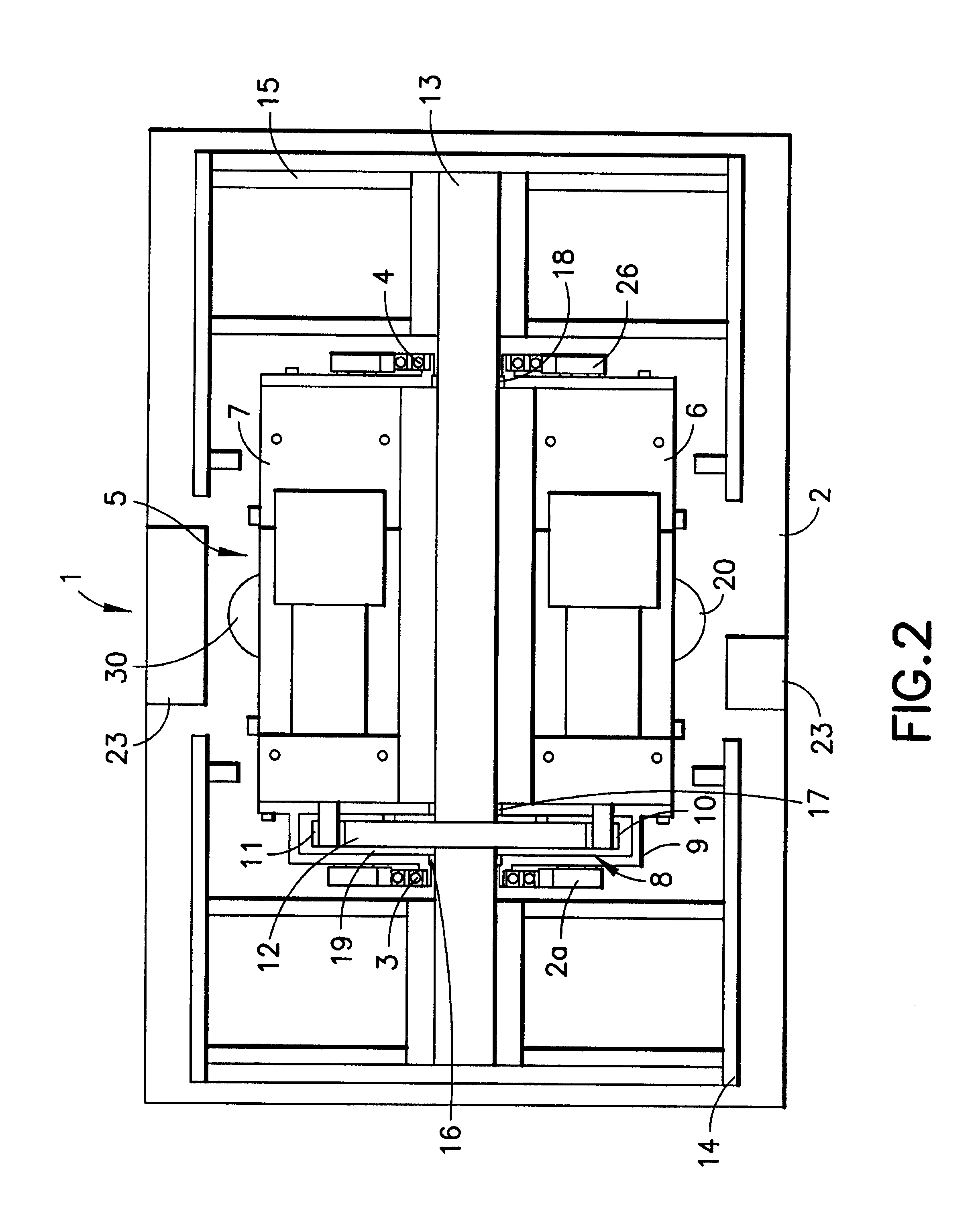
Referring now to FIG. 2, a plan view of the present invention is shown. The motor / transmission combination 5 comprises a first motor 6, a further motor 7, a transmission 8 and the pivotable frame 9. An electric motor and / or a hydraulic motor is provided as the motor 6, 7.

The transmission 8 comprises two pinions 10, 11, which are arranged directly on the motors 6, 7, and a gearwheel 12, which meshes with the pinions 10, 11. The gearwheel 12 is arranged on a shaft 13. Running rollers 14, 15 are arranged at both ends of the shaft 13.

The shaft 13 is mounted on the frame 9 by means of bearing elements 16, 17, 18. The motor...


PUM

PropertyMeasurementUnit
tensile forcesaaaaaaaaaa
resistanceaaaaaaaaaa
constant volume flowaaaaaaaaaa

Abstract

A roller type test stand for motor vehicles and / or wheel / tire combinations including at least one running roller for supporting the wheels, a supporting frame and a drive arranged between the running rollers. The drive is a motor / transmission combination including a shaft for supporting the running rollers, a transmission and at least one motor. The motor is arranged next to the shaft and is connected to the shaft via a transmission. The motor / transmission combination is arranged on a frame that is swing mounted on the supporting frame. At least one measuring apparatus is arranged on the frame between the running rollers. Alternatively, the frame may be replaced by a housing.

Description

1. Field of the InventionThe present invention relates to a roller type test stand for motor vehicles and / or wheel / tire combinations. More particularly, the present inventions relations to a roller type test stand where bearings, lubrication devices and measuring equipment are prevented from introducing error into the test results.2. Description of the Related ArtIn testing vehicle dynamics parameters and exhaust emissions of motor vehicles driven by internal combustion engines, roller or drum type test stands are used that allow various driving conditions to be simulated. For example, in performing tests on braking functions, exhaust emissions, or the like, the vehicle to be tested is fixed in the correct position in the roller type test stand. Either both wheels of one axle or both wheels of several axles standing on the vertex region of respective pairs of running rollers, depending on the design of the test stand. The pairs of running rollers are coupled to driving and decelerat...

Claims


Application Information

Patent Timeline
Patent Type & Authority Patents(United States)
IPC IPC(8): G01M17/02G01M17/06G01M17/007G01L5/28
CPCG01L5/282G01M17/0074G01M17/022G01M17/065
Inventor CORDES, JORG
Owner RENK AG
Learn More