Method and device for transporting heat energy that is produced in a motor vehicle

a technology of motor vehicles and heat energy, which is applied in the direction of mechanical equipment, transportation and packaging, machines/engines, etc., can solve the problems of energy produced in vehicle parts in their operation mostly going unused and emitted without being controlled to the environmen

Inactive Publication Date: 2003-08-05
ROBERT BOSCH GMBH
View PDF8 Cites 48 Cited by
  • Summary
  • Abstract
  • Description
  • Claims
  • Application Information

AI Technical Summary

Problems solved by technology

Until now, the energy produced in vehicle parts in their operation mostl

Method used


Image

  • Method and device for transporting heat energy that is produced in a motor vehicle
  • Method and device for transporting heat energy that is produced in a motor vehicle
  • Method and device for transporting heat energy that is produced in a motor vehicle

Examples


Embodiment Construction

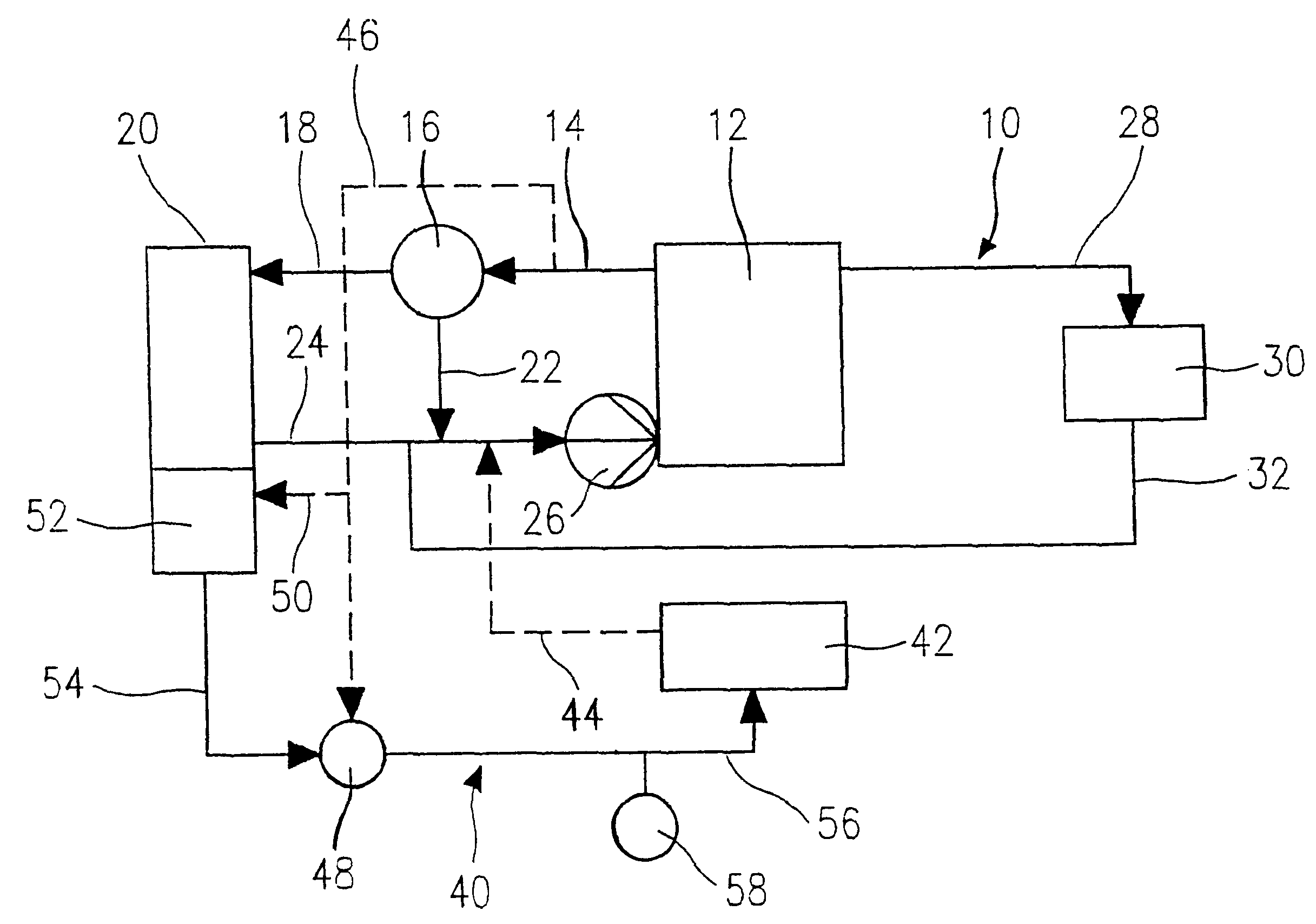
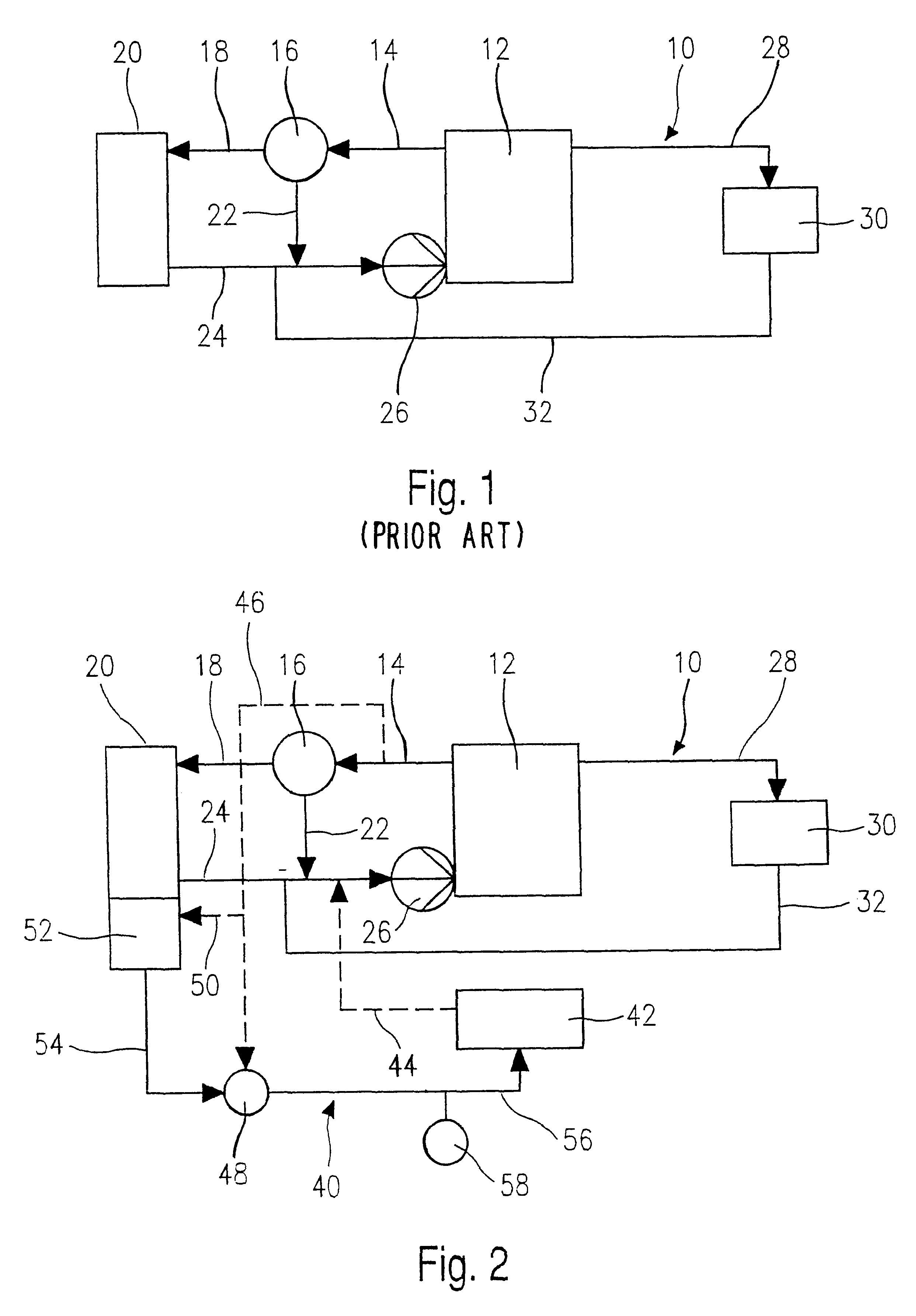
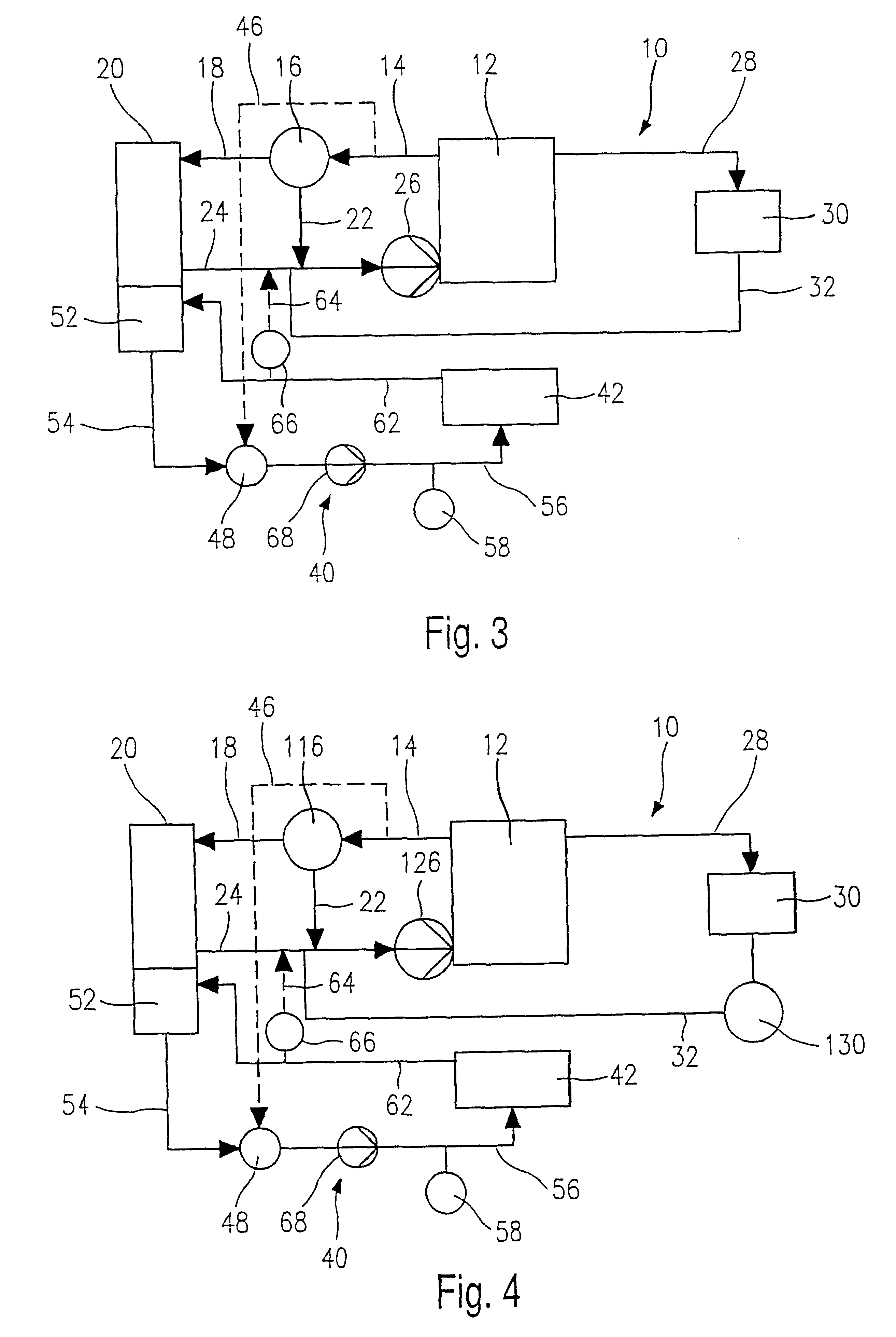
FIG. 1 shows a known coolant circuit 10 of an internal combustion engine 12 of a motor vehicle. From the engine 12, a line 14 leads from the coolant circuit 10 to a thermostat valve 16. From the thermostat valve 16, a line 18 branches off to a radiator 20, and a line 22 branches off to a connecting line 24 between a radiator 20 and a mechanical coolant pump 26 coupled to the engine 12. The coolant pump 26 in turn communicates fluidically with the engine 12. From the engine 12, a line 28 branches off to a heating-type heat exchanger 30, which is used to heat the passenger compartment. On the outlet side, a line 32 connects the heating-type heat exchanger 30 to the connecting line 24.

At coolant temperatures below approximately 90.degree. C., the thermostat valve 16 allows only one flow line of the coolant, arriving via the line 14, via the line 22 to the connecting line 24. If the coolant temperature exceeds 90.degree. C., however, the thermostat valve 26 opens the circuit toward the ...


PUM


Abstract

A method and an apparatus for transporting thermal energy produced in a motor vehicle provides that the waste heat of an electronic component (42), such as a pulse-controlled inverter, be utilized to heat other vehicle parts, such as the internal combustion engine (12) or the passenger compartment. To that end, preferably two coolant circuits (10, 40) are provided, which can be coupled to one another or decoupled from another in order to control the flow of heat.

Description

PRIOR ARTThe invention relates to a method and an apparatus for transporting thermal energy produced in a motor vehicle.Until now, the energy produced in vehicle parts in their operation mostly goes unused and is emitted without being controlled to the environment. Only in the case of the internal combustion engine is the thermal energy contained in its coolant circuit utilized to heat the passenger compartment, via a heating-type heat exchanger.The object of the invention is to create a method and an apparatus by means of which the thermal energy produced in operation of the motor vehicle is utilized in such a way as to reduce the energy consumption of the motor vehicle.ADVANTAGES OF THE INVENTIONThis is attained by a method that is characterized by the follow steps:an electronic component in the motor vehicle is cooled, andthe thermal energy dissipated upon cooling of the component is conducted onward to some other vehicle part to heat it.The invention is furthermore attained by a...

Claims


Application Information

Patent Timeline
IPC IPC(8): B60H1/03B60H1/02F01P3/20F01P7/16F01P7/14F01P5/00F01P5/12B60H1/00B60H1/14B60H1/22
CPCB60H1/03F01P3/20F01P7/164F01P2005/125F01P2007/146F01P2025/08F01P2025/46F01P2050/24F01P2050/30F01P2060/185B60H1/32B60H2001/3286
Inventor HOHL, REINER
Owner ROBERT BOSCH GMBH
Why Eureka
Try Eureka