Screen support and screens for shale shakers

a technology of shale shakers and screens, which is applied in the direction of filtration separation, wellbore/well accessories, separation processes, etc., can solve the problems of large damage to screens, wear of the area at which materials are placed, and wear of parts of screens, so as to increase the life of screens

Inactive Publication Date: 2003-08-05
VARCO I P INC
View PDF51 Cites 39 Cited by
  • Summary
  • Abstract
  • Description
  • Claims
  • Application Information

AI Technical Summary

Benefits of technology

The present invention discloses, in at least certain aspects, a support for a screen or screen assembly for a shale shaker or other vibratory separator. Such a support has at least two areas, including a first areas with a series of typical holes, perforations, or openings as in various prior art screens and screen assemblies; and at least one second area located at a material introduction area in which the holes, etc. are smaller than the holes, etc. in the first area and / or in which the holes, etc. are spaced further apart from each other than are the holes, etc. in the first area. Thus, in certain aspects of the present invention, there is more structure and / or mass in the second area than in the first area so that the second area does not wear as quickly as it would if its holes, etc. were like the holes, etc. of the first area. In one aspect the support is one integral piece with different holes and / or holes with different size and / or holes with different shapes and / or holes spaced differently; and, in other aspects, the support is a primary piece with one or more secondary pieces thereon whose effect is to produce a the different holes etc.
Screens according to certain aspects of the present invention may be made with plastic grids with holes, etc. that correspond to the holes, etc. of a support according to the present invention. In one aspect, the effective opening size of holes or openings at a fluid introduction area of a screen assembly is reduced by adding plastic, glue, epoxy and / or other adhesive around the holes in the fluid introduction area, thus strengthening this area. Also, such material can cross over and / or extend within and / or line the sides of a hole or opening in a support. In another aspect, the different holes, etc. are produced by a pattern of hot melt glue.
When a basket in a shaker has one elevated end (as shown in FIG. 23) so that the separated solids run "uphill", liquid is prevented from running off the screen's exit end; and a pool of liquid can be formed at the basket's opposite end. Teachings of the present invention for material introduction areas can also be used at the screen areas beneath such a pool.
The present invention discloses, in certain aspects, a method for reducing the wear on certain screen areas by using a screen or screens according to the present invention with screen supports according to the present invention.
A system with any such screen support that has relatively increased screen life.

Problems solved by technology

Often there is wear in the area at which material is first introduced to a screen.
Fluid alone and / or abrasive and solids in some fluids can wear away parts of a screen in the material introduction area.
Such wear can cause so much damage to a screen that, although the remainder of the screen is serviceable, the screen must be repaired or replaced.

Method used


Image

  • Screen support and screens for shale shakers
  • Screen support and screens for shale shakers
  • Screen support and screens for shale shakers

Examples


Embodiment Construction

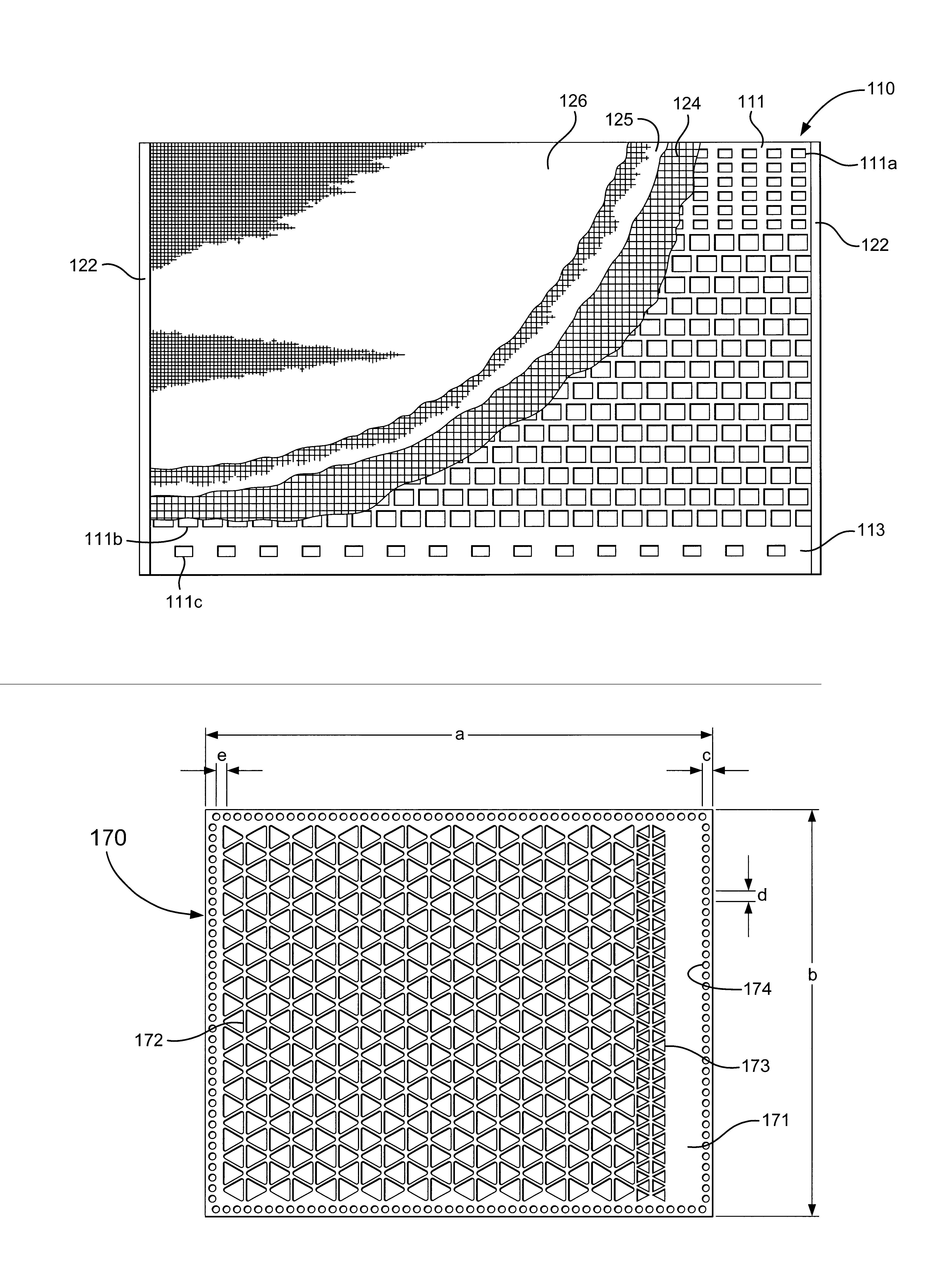
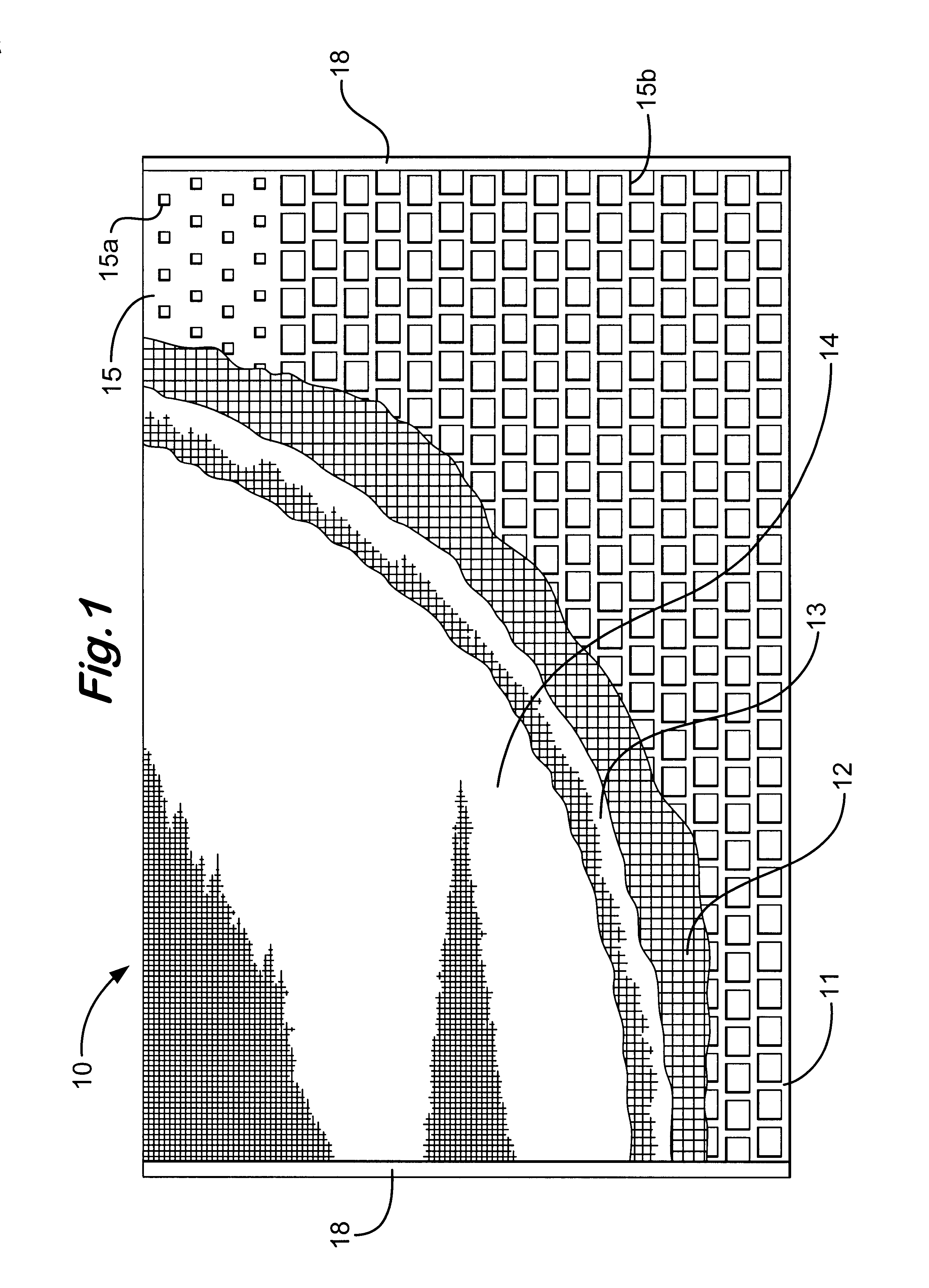
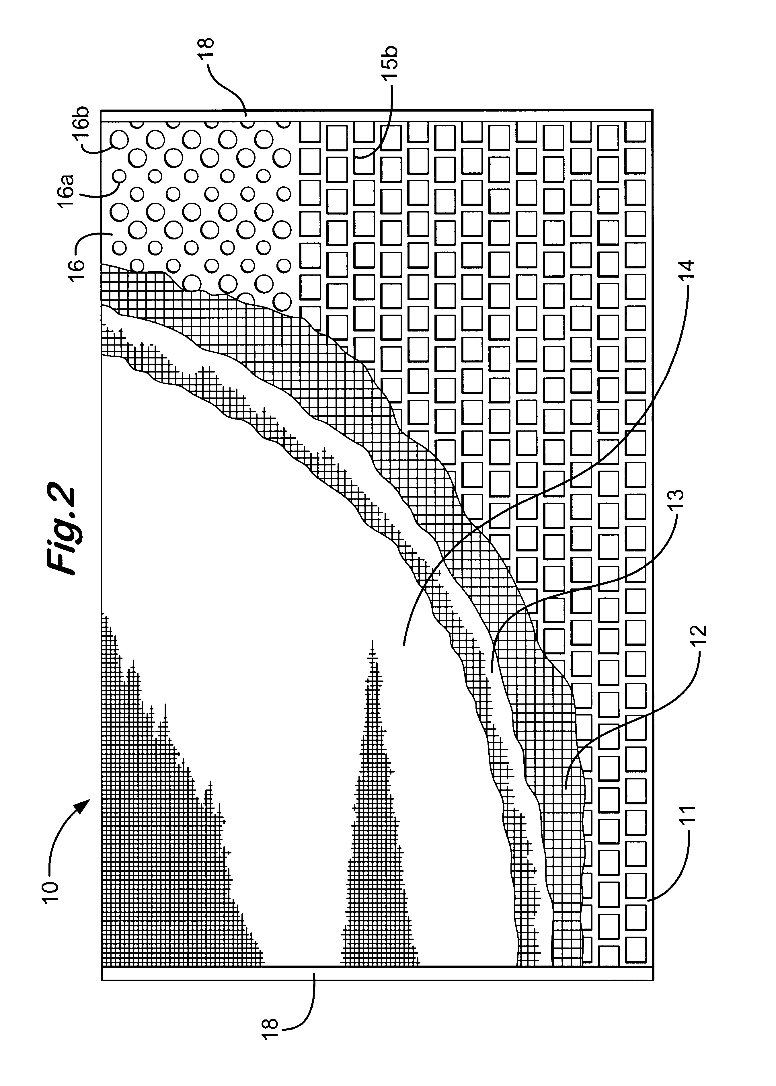
FIG. 1 shows a screen 10 according to the present invention which has a perforated plate 11 on which are mounted three layers 12, 13, and 14 of mesh or screening material. Any of the layers may be deleted. The plate 11 has hookstrips 18 on two of its sides for mounting the screen 10 is suitable shale shakers or vibratory separators. Optionally, the hookstrips are deleted (as may be done with the screens of FIGS. 2-4) and / or the screening material is mounted on a frame or strip support instead of the plate 11. The screen 10 may be like a screen disclosed in U.S. Pat. Des. No. 366,040 (incorporated fully herein for all purposes) and U.S. Pat. No. 5,971,159 (incorporated fully herein for all purposes), but with the holes in the plate 11 as described below.

The plate 11 has a series of holes or openings 15b therethrough which extend over a substantial portion of the plate's entire area. An area 15 of the plate 11 which extends from one side of the plate to the other has a series of holes...


PUM

PropertyMeasurementUnit
thickaaaaaaaaaa
opening sizeaaaaaaaaaa
areaaaaaaaaaaa

Abstract

A support for a screen assembly for a vibratory separator, a screen assembly with such a support, a vibratory separator with one or more such screen assemblies, and a method of using such a screen assembly, such a support having a body, a first series of holes through the body each hole having a first opening size as viewed from above, a second series of holes through the body each hole with a second opening size as viewed from above, the second series of holes at a selected area of the body and the support positionable in a vibratory separator so that the selected area is adjacent a selected location with respect to the vibratory separator, and the second opening size smaller than the first opening size and / or the second series of holes with holes spaced apart differently than the holes of the first series of holes; and in one aspect, a plastic grid with such hole series for fusing together layers of screening material.

Description

1. Field of the InventionThe present invention is directed to screens for vibratory separators and shale shakers, supports for such screens, vibratory separators and shale shakers with such screens, and methods of using such supports, screens, separators, and shakers.2. Description of Related ArtVibratory separators are used in a wide variety of industries to separate materials such as liquids from solids or solids from solids. Typically such separators have a basket or other screen holding or mounting apparatus mounted in or over a receiving receptacle or tank and vibrating apparatus for vibrating the basket. One or more screens is mounted in the basket. Material to be treated is introduced to the screen(s) either by flowing it directly onto the screen(s) or by flowing it into a container, tank, or "possum belly" from which it then flows to the screen(s). Also in some multi-screen apparatuses material flows from an upper screen onto a lower screen.Often there is wear in the area at...

Claims


Application Information

Patent Timeline
Patent Type & Authority Patents(United States)
IPC IPC(8): B01D33/00B07B1/46B01D29/01B01D29/07B01D33/01B01D33/03B07B1/48E21B21/06
CPCB01D29/012B01D29/07B01D33/0093B01D33/0183B01D33/0376B01D33/0384B07B1/46B07B1/4618B07B1/4627B07B1/4645B07B1/4654B07B1/4663B07B1/4672B07B1/469B07B1/48E21B21/06E21B21/065B01D33/41B01D29/52B01D29/72B01D29/445B01D33/0191B01D2201/0415B01D2201/188B07B2201/04
Inventor SCHULTE, JR., DAVID L.MCCLUNG, III, GUY L.
Owner VARCO I P INC
Why Eureka
Try Eureka