External electrode driven discharge lamp

a discharge lamp and external electrode technology, applied in the direction of gas discharge lamp details, electric discharge tubes, electrical apparatus, etc., can solve the problems of internal electrode discharge lamps, failure of discharge lamps, and reduced lifetime of discharge lamps, so as to reduce the maximum voltage requirement, and save energy and cost.

Inactive Publication Date: 2003-08-05
CORNING INC
View PDF30 Cites 14 Cited by
  • Summary
  • Abstract
  • Description
  • Claims
  • Application Information

AI Technical Summary

Benefits of technology

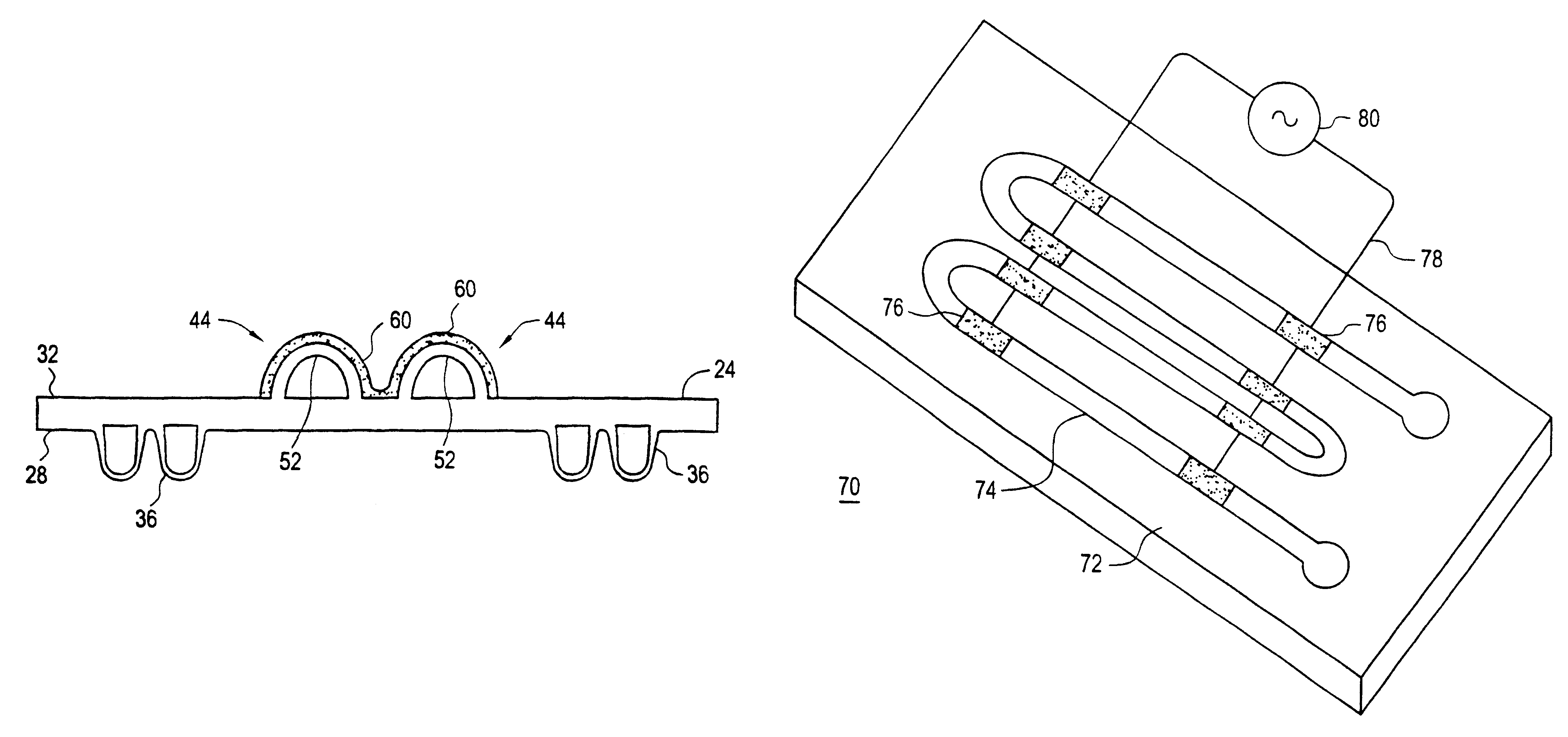
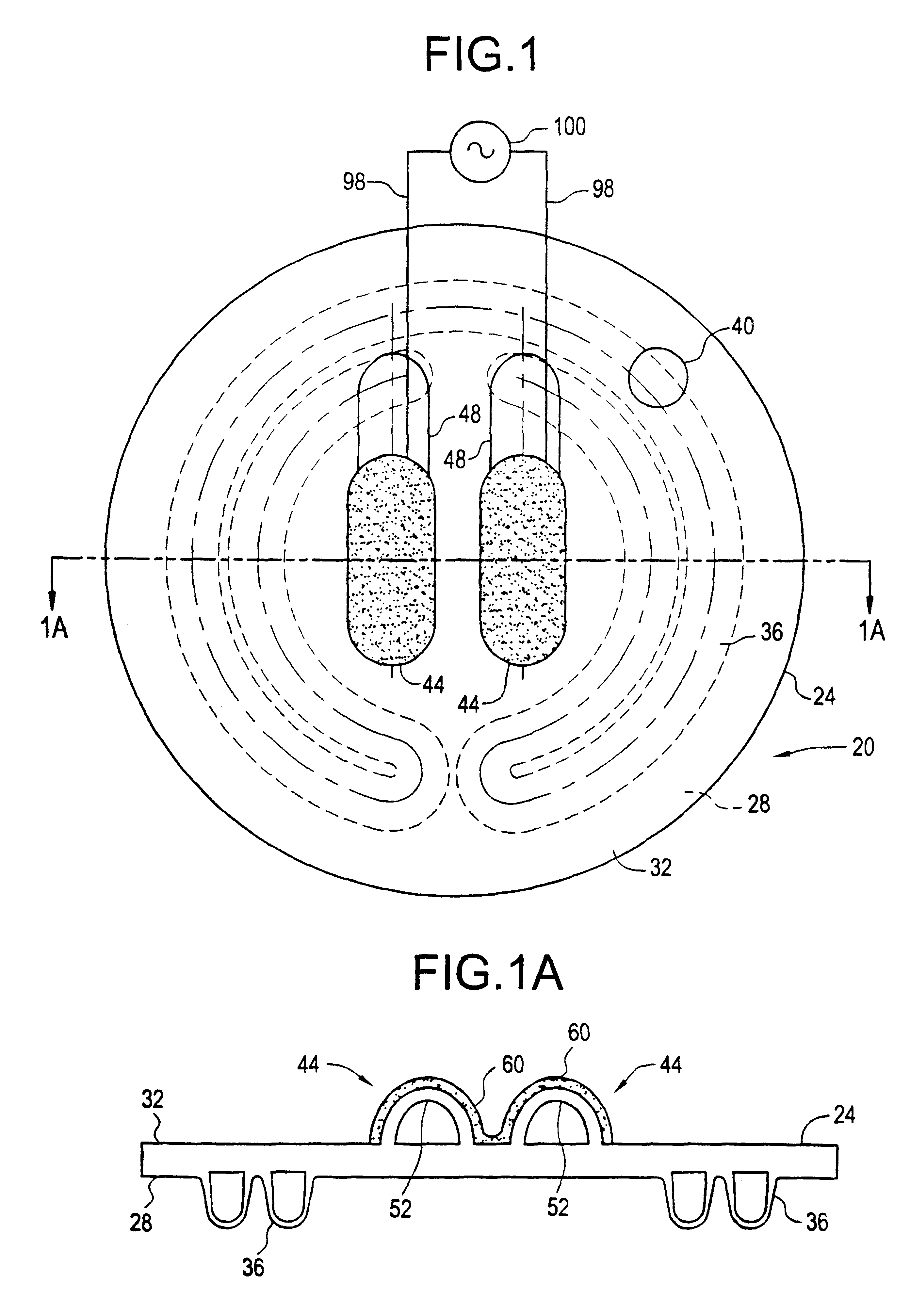
An object of the present invention is to provide a discharge lamp for use in automotive rear lighting applications having packaging simplicity, long life, energy and cost efficiency by employing external electrodes to drive an electrical gas discharge confined within a laminated envelope.
Another object of the present invention is to optimize the capacitive reactance the external electrode site by manipulating the electrode's geometry with the laminated envelope forming process.
According to the present invention, these and other objects and advantages are achieved in.a discharge lamp comprising a laminated envelope and external electrodes for inducing an electrical gas discharge. The laminated envelope comprises at least one gas-discharge channel and an ionizable gas confined within the gas discharge channel. The ionizable gas is activated by external electrodes

Problems solved by technology

A significant problem associated with low-pressure discharge lamps comprising internal electrodes is a reduction in lifetime due to electrode failure resulting from bombardment of the electrode by gas ions, and sputtering away of material from the electrode.
Further, failure in these discharge lamps is also associated with l

Method used


Image

  • External electrode driven discharge lamp
  • External electrode driven discharge lamp
  • External electrode driven discharge lamp

Examples


examples 1 , 2

Examples 1, 2, and 3 have an electrode thickness of 0.75 mm, and Example 4 has an electrode thickness of 0.50 mm.

The power source for the internal electrodes was a 30 mA DC driven ballast. The operating point was chosen as the point at which the light emitting efficiency was the greatest, i.e., at a lamp resistance of 50 kohm. An equal light output condition was maintained for the internal and external electrode configurations. The power source for the external electrodes was a variable frequency plasma generator.

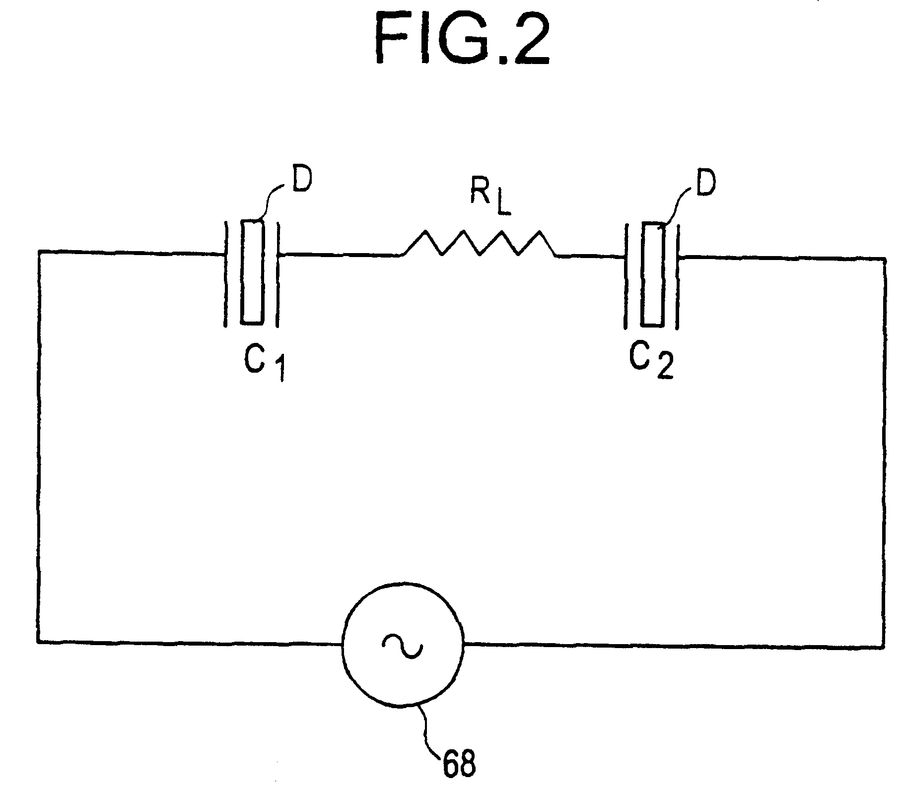
It has been observed that there is no fundamental difference in how power is applied to the discharge lamps of the following Table, i.e., whether the discharge is driven by internal or external electrode configurations, as long as the circuit is tuned to the proper operating frequency when driving through external electrodes, i.e., the frequency at which the greatest light emitting efficiency is achieved. In the laboratory experiment examples tuning was achieved with a vari...


PUM


Abstract

A discharge lamp (20), such as a neon lamp, comprising a laminated envelope having a gas-discharge channel and at least one external electrode (44) in communication with the gas-discharge channel (20), the laminated envelope having a front surface (32) and a back surface (28) integrated together to form a unitary envelope body essentially free of any sealing materials. The external electrode (44) comprises an electrode surface integral with the laminated envelope and a conductive medium disposed on the electrode surface. The conductive medium may be conductive tape, conductive ink, conductive coatings, frit with conductive filler or conductive epoxies. The discharge lamp may comprise a laminated envelope including a plurality of separate gas-discharge channels and external electrodes in communication with the gas-discharge channels, whereby the discharge is driven in parallel.

Description

BACKGROUND OF INVENTION1. Field of InventionThe present invention relates to a low-pressure discharge lamp in which external electrodes are employed to drive an electrical gas discharge confined within a laminated envelope. More particularly the present invention relates to such a discharge lamp which could be utilized for the purpose of automotive rear lighting applications.2. Description of Related ArtIn the neon signage industry, the standard type of electrode employed in low-pressure discharge lamps is the internal electrode. Internal electrodes, as the name provides, are located within the glass tubing and typically consist of a metal shell coated with an emissive coating. A connection to an external power source is made via a wire which is glass-to-metal sealed in the tubing see generally W. Strattman, Neon Techniques, Handbook of Neon Sign and Cold Cathode Lighting, ST Publications, Inc., Cincinnati, Ohio (1997).A significant problem associated with low-pressure discharge lam...

Claims


Application Information

Patent Timeline
IPC IPC(8): H01J61/30H01J65/04H01J11/00H01J65/00
CPCH01J61/305H01J65/046H01J61/30H01J65/00H01J65/04
Inventor TRENTELMAN, JACKSON P.
Owner CORNING INC
Why Eureka
Try Eureka