Transmitter-receiver, and method for controlling transmission power of the same

a technology of transmission power and receiver, applied in power management, multiplex communication, wireless communication, etc., can solve the problems poor traceability, and appropriately controlling transmitting power, and achieve the effect of reducing data transmission efficiency

Inactive Publication Date: 2003-08-05
PANASONIC CORP
View PDF11 Cites 41 Cited by
  • Summary
  • Abstract
  • Description
  • Claims
  • Application Information

AI Technical Summary

Benefits of technology

It is an objective of the present invention to provide a transmission / reception apparatus and its transmit power control method combining trackability during fast fading or when a compressed mode is applied and stability during slow fading without reducing data transmission efficiency.

Problems solved by technology

However, in the conventional transmission / reception apparatus and transmit power control method, since an amount of the increase or decrease during transmit power control, that is, a range of transmit power to be increased or decreased based on a TPC bit made up of one received bit is a predetermined fixed value (.+-.1 dB in the example above), if this fixed value is too large, it is difficult to control transmit power appropriately and maintain stability when amplitude variations are small (during slow fading), whereas if this fixed value is too small, poor traceability results when there are considerable amplitude variations (during fast fading).
However, since the number of bits within one slot is fixed, increasing the number of bits used as TPC bits will cause a problem of reducing data transmission efficiency.
Moreover, in the above example, control is limited to increasing or decreasing transmit power even if transmit power is appropriate and it is preferable to maintain the current value, and thus it is not possible to maintain a fixed value, ending up repeating increases and decreases in short cycles centered on an appropriate value.

Method used


Image

  • Transmitter-receiver, and method for controlling transmission power of the same
  • Transmitter-receiver, and method for controlling transmission power of the same
  • Transmitter-receiver, and method for controlling transmission power of the same

Examples


embodiment 1

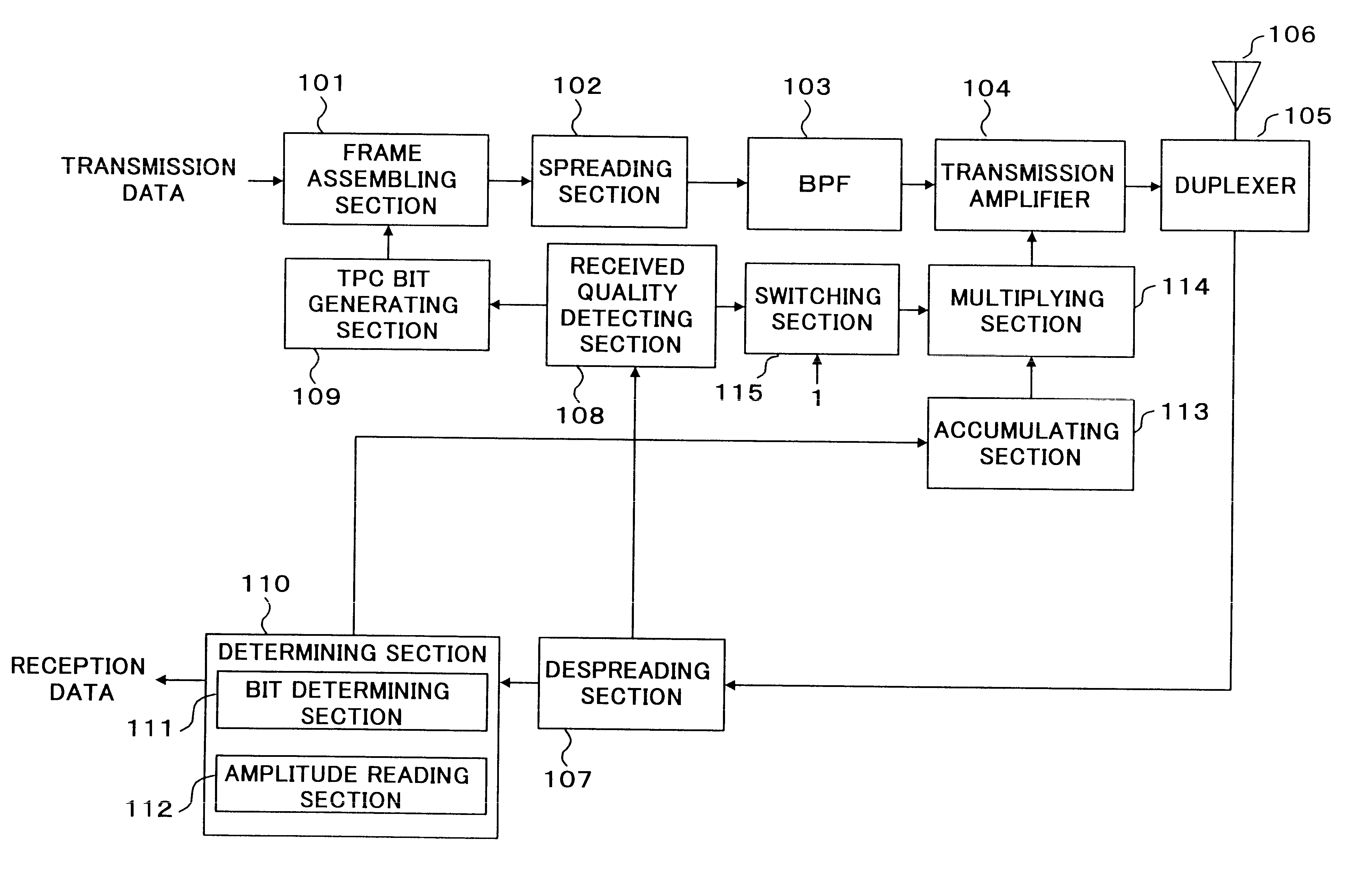
Then, the configuration of received quality detecting section 108 is described in detail using FIG. 3. FIG.3 is a main block diagram showing an outlined configuration of the received quality detecting section according to

For a despread signal entered in received quality detecting section 108, an SIR is measured by SIR measuring section 201 first. Subtracting section 202 subtracts a reference SIR retained by storing section 203 from the SIR of the measured reception signal (hereinafter referred to as "measured SIR") and sends the result to positive / negative determining section 204. Positive / negative determining section 204 determines whether the subtraction result is positive or negative and sends the result to TPC bit generating section 109. This allows TPC bit generating section 109 to determine 0 or 1, that is, whether to instruct to increase or decrease transmit power and generate the bit.

Dividing section 205 calculates the ratio of the measured SIR to the reference SIR and sends...

embodiment 2

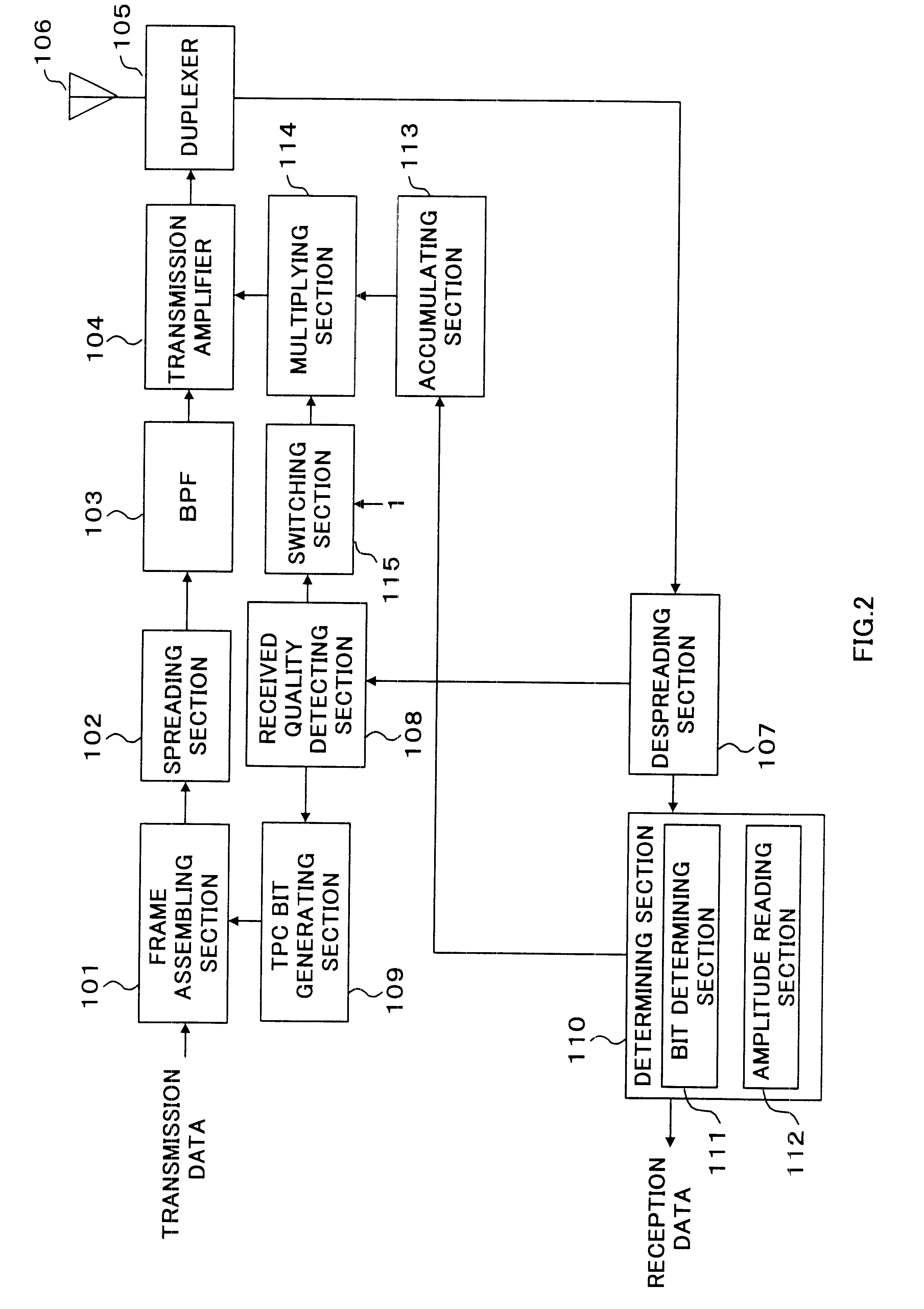
The transmission / reception apparatus according to the present embodiment has the same configuration as that in Embodiment 1, provided, however, with a limiter to prevent the transmission amplifier from being requested to increase transmit power excessively.

The limiter can be placed 1) between the multiplying section and transmission amplifier, 2) between the received quality detecting section and switching section, 3) between the accumulating section and multiplying section and 4) between the determining section and accumulating section. Cases 1) to 4) will be explained below using FIG. 4 to FIG. 7. The parts with the same configuration as that in Embodiment 1 are assigned the same codes and their detailed explanations are omitted.

The configuration of the transmission / reception apparatus when a limiter is placed 1) between the multiplying section and transmission amplifier is shown in FIG. 4. In FIG. 4, an amplitude control value of transmit power sent from multiplying section 114 t...

embodiment 3

The present embodiment explains a case where in compressed mode, an increase or decrease and an amount of the increase or decrease of transmit power are indicated by the symbol and amplitude of the TPC bit. Here, the compressed mode refers to a mode in which the spreading factor for data being transmitted continuously is reduced and transmission is performed with power of the part corresponding to the changed spreading factor increased instead, thus compressing the transmission time as shown in FIG. 9 and FIG. 10. The compressed mode is sometimes also called "slotted mode."

The compressed mode allows other carriers to be monitored during a free time spared by compressing the transmission time. This allows information of different carriers to be monitored without reducing the amount of information transmitted during a communication. In this case, it is possible to monitor the communication and different carriers through a single reception section.

For example, if the spreading factor c...


PUM


Abstract

Received quality detecting section 108 detects a received quality, bit determining section 111 determines whether a TPC bit is 0 or 1, amplitude reading section 112 reads a ratio of an amplitude of a signal other than the TPC bit and an amplitude of the TPC bit, accumulating section 113 determines an increase or decrease of transmit power and an amount of the increase and decrease of the transmit power using a symbol of the TPC bit for the increase or decrease, and an amplitude ratio for the amount of the increase and decrease to instruct to transmission amplifier 104, and multiplying section 114 multiplies the amplitude of the signal other than the TPC bit by a correction value corresponding to the received quality to determine the amplitude of the TPC bit.

Description

The present invention relates to a transmission / reception apparatus and its transmit power control method of a mobile communication using a CDMA system.A transmission / reception apparatus and its transmit power control method in a conventional mobile communication are explained using FIG. 20. FIG. 1 is a main block diagram showing an outlined configuration of a conventional transmission / reception apparatus.Frame assembling section 1 multiplexes transmission data with a TPC bit. Spreading section 2 spreads / modulates the multiplexed data and BPF 3 eliminates an unnecessary signal from the spread / modulated signal. Transmission amplifier 4 amplifies the transmission signal stripped of the unnecessary signal. Duplexer 5 controls an input / output signal to / from antenna 6. Antenna 6 radiates the amplified transmission signal.Antenna 6 receives a transmitted signal. Despreading section 7 demodulates the reception signal. At this time, received quality detecting section 8 detects a received qu...

Claims


Application Information

Patent Timeline
Patent Type & Authority Patents(United States)
IPC IPC(8): H04B7/005H04W52/04H04B1/04H04B7/26H04J13/00H04W52/44H04W52/54
CPCH04W52/04H04W52/223H04W52/283H04W52/288H04W52/54H04W52/24H04W52/36H04W52/44Y02B60/50H04B1/04
Inventor KITAGAWA, KEIICHIUESUGI, MITSURUMIYA, KAZUYUKIKASAPIDIS, MAKIS
Owner PANASONIC CORP
Why Eureka
Try Eureka